Exporting Files: 1:1 PDF (Iron-On) and Gerber (Send to Fab)
Both buttons are in the left panel, Export tab (next to "Tools").
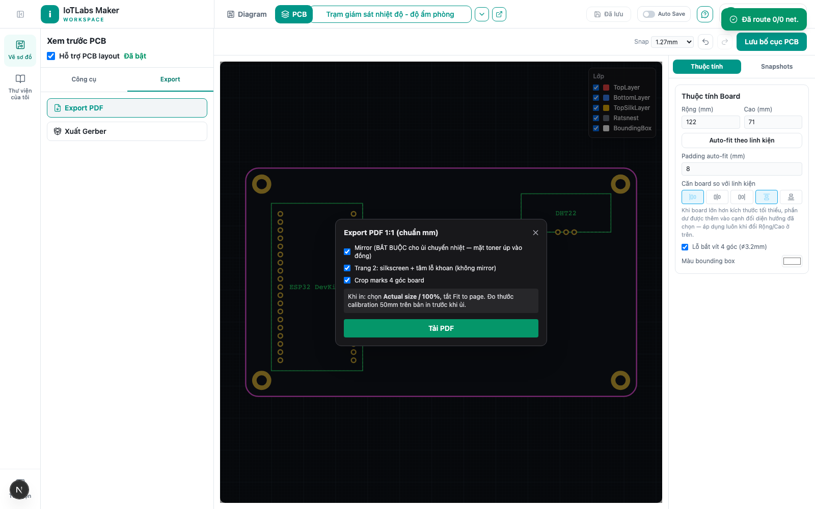
Export PDF
- Click Export PDF.
- If there are still crossing errors: "Export blocked: N trace crossings remaining. See 'Auto-Fix Errors' to find where, then add a jumper manually or reroute the wire."
- If not blocked, the "Export PDF 1:1 (mm accurate)" dialog has:
- Mirror (enabled by default, "REQUIRED for heat-transfer ironing — toner side faces the copper").
- Page 2: silkscreen + drill centers (not mirrored).
- Crop marks at the 4 board corners.
- A warning if the board is larger than A4 ("the printout will be cropped, not automatically scaled down").
- A note: "When printing: choose Actual size / 100%, and turn off Fit to page. Measure the 50mm calibration ruler on the printout before ironing."
- Click Download PDF.
Result: a file pcb-<project-id>.pdf is created, drawn to an accurate 1:1 mm scale (not a screenshot). Page 1 is the mirrored black-and-white version, including the outline, copper traces, pads/drill holes, crop marks, and a 50mm calibration ruler + a 10×10mm reference square to re-measure before ironing. Page 2 (if enabled) is NOT mirrored, used for drilling/assembly alignment.
Checking the printout before ironing the board
Before actually ironing, always check the paper printout first:
- Use a ruler to measure the 2.54mm header spacing, the spacing between the two rows of ESP32 pins, and the board's overall size on the printout — even a 2–3% deviation caused by the printer's "Fit to page" setting can make headers not line up with the real components.
- Place the real components on the paper: check whether the ESP32 pins, relay, LED, and terminal align with the correct pads, and whether the USB port faces the correct direction (especially important for ESP32 DevKit boards).
- A laser printer gives the best toner-transfer results; a direct-thermal receipt/thermal-paper printer doesn't produce a toner layer, so it should only be used to print a drill-alignment template, not for actually transferring the real circuit.
Export Gerber
- In the Export tab, click Export Gerber.
Result: a file pcb-gerber-<project-id>.zip containing pcb-F_Cu.gbr, pcb-B_Cu.gbr, pcb-Edge_Cuts.gbr, pcb-F_SilkS.gbr, pcb-PTH.drl, README.txt — upload it directly to JLCPCB/PCBWay. This is also blocked if there are still crossing errors.
Example
Making the "Room Temperature & Humidity Monitoring Station" board at home using the toner-transfer method: check that DRC is clean, click "Export PDF", keep Mirror enabled as it is by default, download the PDF, print at Actual size 100% on a laser printer, then measure the 10×10mm square on the printout with a ruler before ironing it onto the copper board — if the square measures exactly 10×10mm, the whole layout is guaranteed to be at an accurate 1:1 scale.