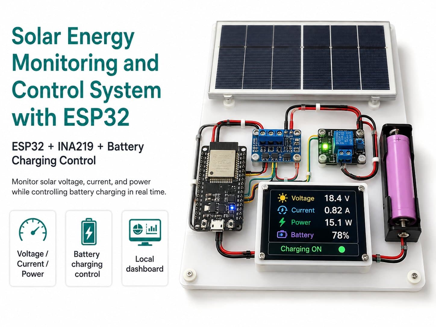
Solar Energy Monitoring and Control System with ESP32
Build a low-voltage DC model using an ESP32 to measure solar voltage, current, and power, monitor a battery, and control a DC load over MQTT.
1. Project Introduction
This project guides you through building a solar energy monitoring and control model using an ESP32, within an educational engineering scope. The system focuses on measuring voltage, current, and power from a solar panel, tracking the storage battery's voltage, and controlling a small DC load over MQTT.
This model suits learning IoT, renewable energy, DC electrical measurement, load control, and building a remote monitoring dashboard. It does not cover connecting to mains AC power, inverters, grid-tied systems, or high-voltage solar panel strings.
2. Technical Goals
| Goal | Description |
|---|---|
| Measuring input energy | Use an INA219 to measure bus voltage, current, and power within the module's allowed range. |
| Monitoring the storage battery | Use a voltage divider to bring the battery voltage down to a level safe for the ESP32's ADC pin. |
| Controlling the DC load | Use a relay or MOSFET module to switch a small DC load on/off, never powering the load directly from a GPIO. |
| Remote monitoring | The ESP32 sends telemetry to MQTT on a regular interval. |
| Basic protection | Automatically turns off the load when battery voltage is low, and only turns it back on once the battery has recovered. |
3. Safety Scope
This project only applies to low-voltage DC systems — a 6V, 9V, or 12V panel is recommended, along with a storage battery with protection circuitry or a matching charger, a small load current, and correctly sized wiring.
⚠️ Do not connect to 220V AC mains power. Do not connect an inverter. Do not connect a grid-tied solar system. Do not work with a high-voltage PV string. If the DC voltage exceeds 50V or the system has significant power, have a qualified electrician check it.
4. System Architecture
Solar Panel
  -> INA219 measures voltage, current, power
  -> Solar Charge Controller
  -> DC Storage Battery
  -> 5V Buck Converter
  -> ESP32

DC Storage Battery
  -> Relay or MOSFET module
  -> Small DC Load

ESP32
  -> MQTT Broker
  -> Monitoring & Control Dashboard
5. System Data
| Data Field | Meaning |
|---|---|
| pv_voltage | The voltage measured at the solar panel line or the monitored source line. |
| pv_current_ma | The current measured through the INA219, in mA. |
| pv_power_mw | Instantaneous power, in mW. |
| battery_voltage | Battery voltage, computed from the voltage divider. |
| load | The DC load's status. |
| mode | AUTO or MANUAL mode. |
6. Pre-Power-On Checklist
Before powering the ESP32, use a multimeter to confirm the battery's polarity, the buck converter's output voltage, the voltage at the ADC pin after the voltage divider, and the expected load current.
✅ Only power on once the buck converter's output is stable, the ADC pin doesn't exceed 3.3V, and the DC load is within the relay's or MOSFET module's rated limits.
Detailed guide
List of extended articles for this project.
Part 1: System Overview
Introduces the low-voltage DC model's architecture and the role of the ESP32, INA219, charge controller, storage battery, DC load, and MQTT.
Part 2: Preparing Components with the Right Specs
Choose the ESP32, panel, charge controller, storage battery, INA219, buck converter, relay/MOSFET, and voltage divider correctly within the low-voltage DC scope.
Part 3: Wiring the ESP32, INA219, Battery, and DC Load
Guides you through wiring the INA219 over I2C, measuring panel current, measuring the battery via a voltage divider, powering the ESP32 through a 5V buck converter, and controlling the DC load.
Part 4: Programming the ESP32 to Measure Energy and Send MQTT Data
Install libraries, configure WiFi and MQTT topics, read the INA219, read the battery via the ADC, send telemetry, and receive DC load control commands.
Part 5: Monitoring and Control Dashboard over MQTT
Design a dashboard showing voltage, current, power, battery voltage, load status, and ON/OFF/AUTO control buttons over MQTT.
Part 6: Testing, Calibrating, and Finalizing the System
Check the power supply, calibrate battery voltage, test MQTT, troubleshoot common issues, and finalize the ESP32 solar energy monitoring model.