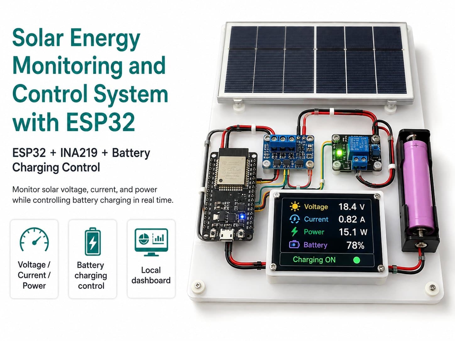
Part 3: Wiring the ESP32, INA219, Battery, and DC Load
Guides you through wiring the INA219 over I2C, measuring panel current, measuring the battery via a voltage divider, powering the ESP32 through a 5V buck converter, and controlling the DC load.
Part 3: Wiring the Hardware
This part guides you through wiring block by block, for easier testing. Never power up the entire system all at once. Wire each part, remeasure with a multimeter, and only then connect the ESP32.
Connecting the INA219 to the ESP32
| INA219 | ESP32 | Function |
|---|---|---|
| VCC | 3V3 | Logic power for the INA219 module, if it supports 3.3V. |
| GND | GND | Common ground. |
| SDA | GPIO21 | I2C data. |
| SCL | GPIO22 | I2C clock. |
Wiring the Current-Sensing Path Through the INA219
Solar Panel +  -> INA219 VIN+
INA219 VIN-    -> Solar Charger PV+
Solar Panel -  -> Solar Charger PV-
This wiring routes current from the panel through the INA219's shunt before reaching the charge controller. If the current reads negative, recheck the VIN+/VIN- direction.
⚠️ Never exceed the INA219 module's rated bus voltage and current limit. The maximum current depends on the shunt resistor and module design, not just the IC.
The Battery-Voltage Divider Circuit
Battery + -> R1 100kΩ -> GPIO34 -> R2 22kΩ -> GNDThe midpoint between R1 and R2 connects to GPIO34. Before plugging it into the ESP32, measure the voltage at this midpoint with a multimeter. The reading must stay below 3.3V under any full-charge condition.
Wiring the Buck Converter to Power the ESP32
| Buck Converter | Connection | Check |
|---|---|---|
| IN+ | Battery + after the charge controller, or a suitable battery output | Correct polarity. |
| IN- | Battery - | Power ground. |
| OUT+ | ESP32 5V/VIN or the USB port | Measure it reads about 5V before plugging in the ESP32. |
| OUT- | ESP32 GND | Common ground. |
Wiring the Relay or MOSFET Load Controller
| Control Module | ESP32 or Power Source | Note |
|---|---|---|
| IN | GPIO26 | Control signal. |
| VCC | Per the module, usually 3.3V or 5V | Check the module's documentation. |
| GND | Common GND | Must share ground with the ESP32 if driven directly. |
| LOAD input | Battery + through a fuse | Never draw load current from the ESP32. |
| LOAD output | DC Load + | The load must match the correct voltage and current. |
✅ After wiring, check in order: battery polarity, the buck converter's 5V output, the GPIO34 voltage after the divider — only then flash the code and apply full power.