Part 6: Testing, Calibrating, and Finalizing the System
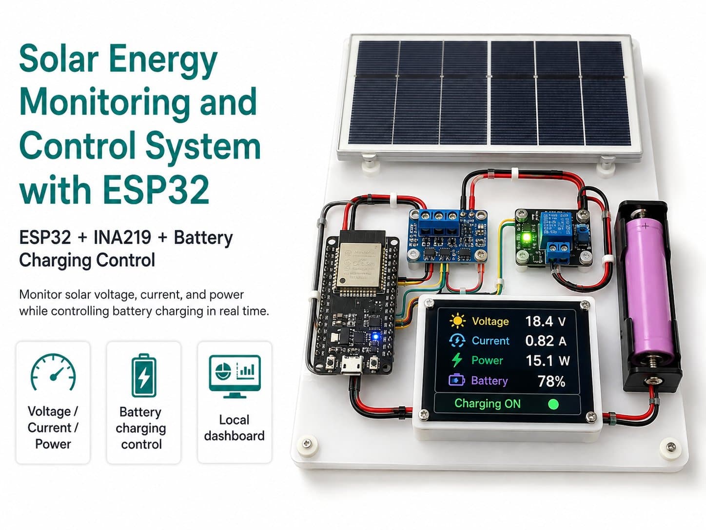
Check the power supply, calibrate battery voltage, test MQTT, troubleshoot common issues, and finalize the ESP32 solar energy monitoring model.
Part 6: Testing, Calibrating, and Finalizing the System
After finishing the hardware and firmware, test in order to avoid powering things up wrong or misreading data. Don't skip the multimeter-measurement steps, since both the ESP32's ADC and the current-sensing module need to be verified against reality.
Checks Before Powering On the ESP32
| Item | How to Check | Pass Condition |
|---|---|---|
| Battery polarity | Measure with a multimeter at the battery terminal and the buck's input | Positive/negative are correct, not reversed. |
| Buck output | Measure OUT+ and OUT- | Stable around 5V before plugging in the ESP32. |
| GPIO34 voltage | Measure the voltage divider's midpoint | Always below 3.3V. |
| Load line | Test continuity and check the fuse | No short, correct load voltage. |
| INA219 I2C | Check SDA, SCL, VCC, GND | Power and ground aren't swapped. |
Calibrating Battery Voltage
Read the battery voltage via the ESP32, then compare it against a multimeter. If there's an error, compute the correction coefficient and update BATTERY_CALIBRATION.
BATTERY_CALIBRATION = multimeter reading / voltage the ESP32 readsFor example, if the multimeter reads 12.40V and the ESP32 reads 12.10V, the correction coefficient is 12.40 divided by 12.10, approximately 1.024.
Testing MQTT
| Step | Action | Expected Result |
|---|---|---|
| Subscribe to telemetry | Watch iotlabs/solar01/telemetry | Receives JSON on a regular interval. |
| Send OFF | Publish OFF to iotlabs/solar01/cmd/load | The load turns off. |
| Send AUTO | Publish AUTO to the control topic | The ESP32 returns to automatic mode. |
| Send ON while the battery is low | Simulate it, or set a high threshold to test | The ESP32 doesn't turn on the load and sends an alert. |
Common Issues
| Issue | Common Cause | Fix |
|---|---|---|
| The ESP32 keeps resetting | A weak buck converter, thin power wires, or the load causing a voltage sag | Use a buck converter with enough current, add a filter capacitor, and separate the load's power supply if needed. |
| The ADC reads incorrectly | A wrong divider, noise, or missing calibration | Remeasure the resistors, average multiple samples, and calibrate against a multimeter. |
| The INA219 current is negative | VIN+ and VIN- are reversed | Recheck the current direction through the shunt. |
| The relay keeps chattering | The on/off thresholds are too close together, or the battery sags when the load turns on | Widen the gap between thresholds and check the load current. |
| MQTT won't connect | A wrong host, port, username, password, or network | Check the broker configuration and WiFi. |
Finishing the Model
Once the circuit runs reliably, mount the modules in an enclosure, use a terminal block for the power wires, mark polarity clearly, add a DC fuse on the load line, and label the connection ports.
✅ A complete system should read stable data, control the load with correct logic, alert on a low battery, and be able to safely cut the load — all within the scope of the low-voltage DC model.