Configuring Pin Count & Layout
Configuring pin count & layout
Under "Pin Count & Layout" there are 4 blocks corresponding to the 4 sides of the board — each block has an on/off checkbox + a pin count field:
- Top
- Bottom
- Left
- Right
- Check the checkbox for the side you want to have pins on (by default, a new module already has Left: 1 and Right: 1 — if you only want a single row of pins, uncheck the other side).
- Enter the pin count for that side in the number field next to it (minimum 1, maximum 99).
- You can enable multiple sides at once (e.g. Left + Right to create a 2-row header, or all 4 sides for an IC/grid-pin board).
Result: The pin list below ("Pin List") automatically generates the correct number of rows matching the total pin count you just configured, and the preview panel on the right updates immediately with the new pin layout.
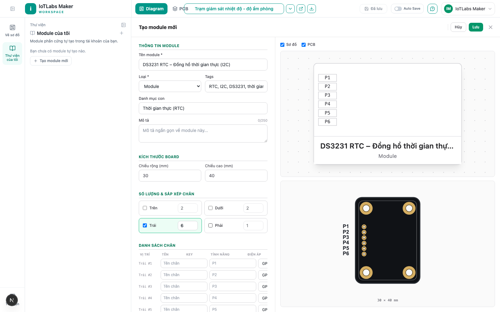
Note: If you enable the Top and/or Bottom sides, the system shows a warning: "Independent preview — the actual diagram will display using a single left/right/top/bottom layout (not all 4 sides at once) once placed in the Workspace." — meaning that once the module is placed on the real Diagram, it will display using a simpler layout than the preview shown in the editor.
Filling in each pin's details
Under "Pin List", each row corresponds to one pin with the following columns:
- Position — auto-generated, display only (e.g. "Left #1"), not editable.
- Name — the pin's display name (e.g. "Power In").
- Key — a short label printed on the preview and the PCB silkscreen (e.g. VCC, GND, SDA); automatically uppercased with diacritics removed. This is just a display label — it does not affect wiring.
- Function — choose the signal type: Power, GND, GPIO, Analog, I2C, SPI, UART.
- Voltage — the operating voltage for that specific pin (e.g. "3.3V").
Result: This pin list is exactly the actual wiring points when you drag the module into the Diagram.
Example
The "DS3231 RTC" module communicates over I2C: enable the Left side, enter 6 pins — then fill in the details: VCC (Power, 3.3V-5V), GND (GND), SDA (I2C), SCL (I2C), SQW (GPIO), 32K (GPIO). When you drag this module into the diagram, all 6 pins appear exactly as configured, ready for Auto Wire to correctly recognize the I2C bus.