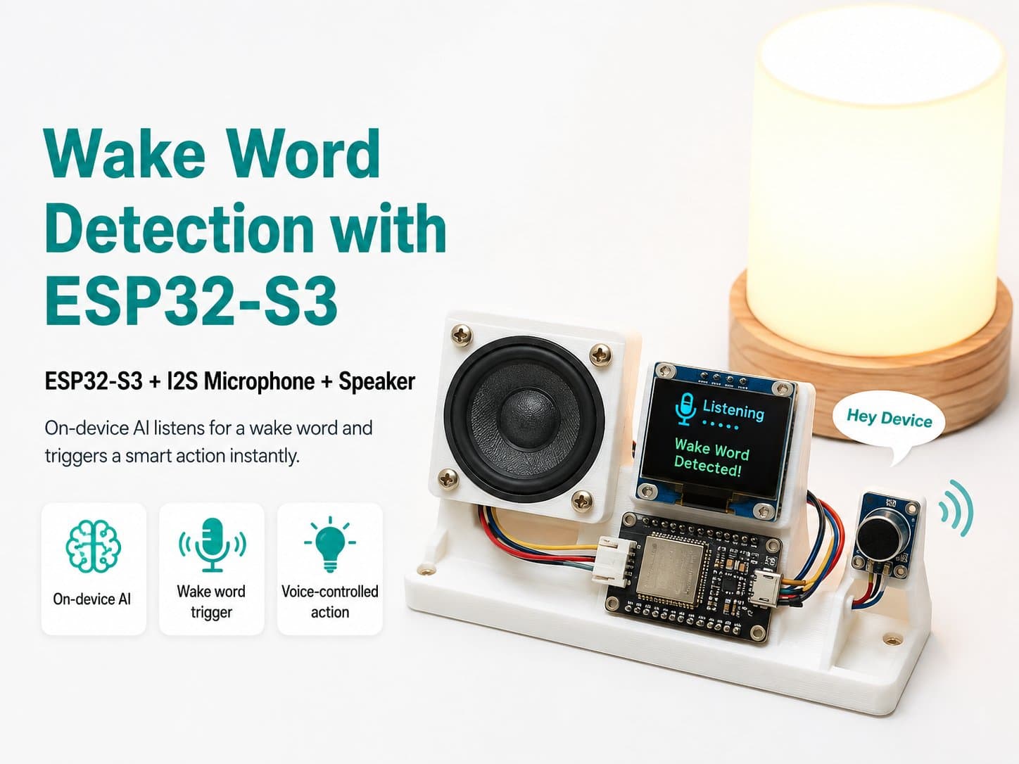
ESP32-S3 to INMP441 I2S Microphone Wiring Diagram
Overview of the ESP32-S3 and INMP441
The ESP32-S3 is a powerful microcontroller with audio-processing capability and WiFi/Bluetooth support. The INMP441 is an I2S microphone that captures high-quality audio, well suited for speech-recognition applications.
Wiring Diagram
Below is the wiring diagram between the ESP32-S3 and the INMP441 microphone:
ESP32-S3 Pin      INMP441 Pin
------------------------------
GPIO 35 (SCK)     SCK
GPIO 36 (WS)      WS
GPIO 37 (SD)      SD
GND               GND
3.3V              VDD
Connection Details
SCK (Serial Clock): connects to GPIO 35, ensuring a high data-transfer rate.
WS (Word Select): connects to GPIO 36, used to control the audio data format.
SD (Serial Data): connects to GPIO 37, where audio data is received from the microphone.
GND: a common ground shared by both devices.
3.3V: supplies power to the INMP441 microphone. Check your specific INMP441 module's voltage requirement before connecting.
Tip: make sure the connections are solid to avoid signal loss while capturing audio.
Programming the ESP32-S3
To use the INMP441 microphone, you need to use the I2S library in the Arduino IDE. Below is a sample snippet to initialize the microphone:
#include

void setup() {
    i2s_config_t i2s_config = {
        .mode = I2S_MODE_MASTER | I2S_MODE_RX,
        .sample_rate = 44100,
        .bits_per_sample = I2S_BITS_PER_SAMPLE_16BIT,
        .channel_format = I2S_CHANNEL_FMT_RIGHT_LEFT,
        .communication_format = I2S_COMM_FORMAT_I2S_MSB,
        .intr_alloc_flags = 0,
        .dma_buf_count = 8,
        .dma_buf_len = 1024,
        .use_apll = false
    };
    i2s_driver_install(I2S_NUM_0, &i2s_config, 0, NULL);

    i2s_pin_config_t pin_config = {
        .bck_io_num = 35,
        .ws_io_num = 36,
        .data_out_num = I2S_PIN_NO_CHANGE,
        .data_in_num = 37
    };
    i2s_set_pin(I2S_NUM_0, &pin_config);
}