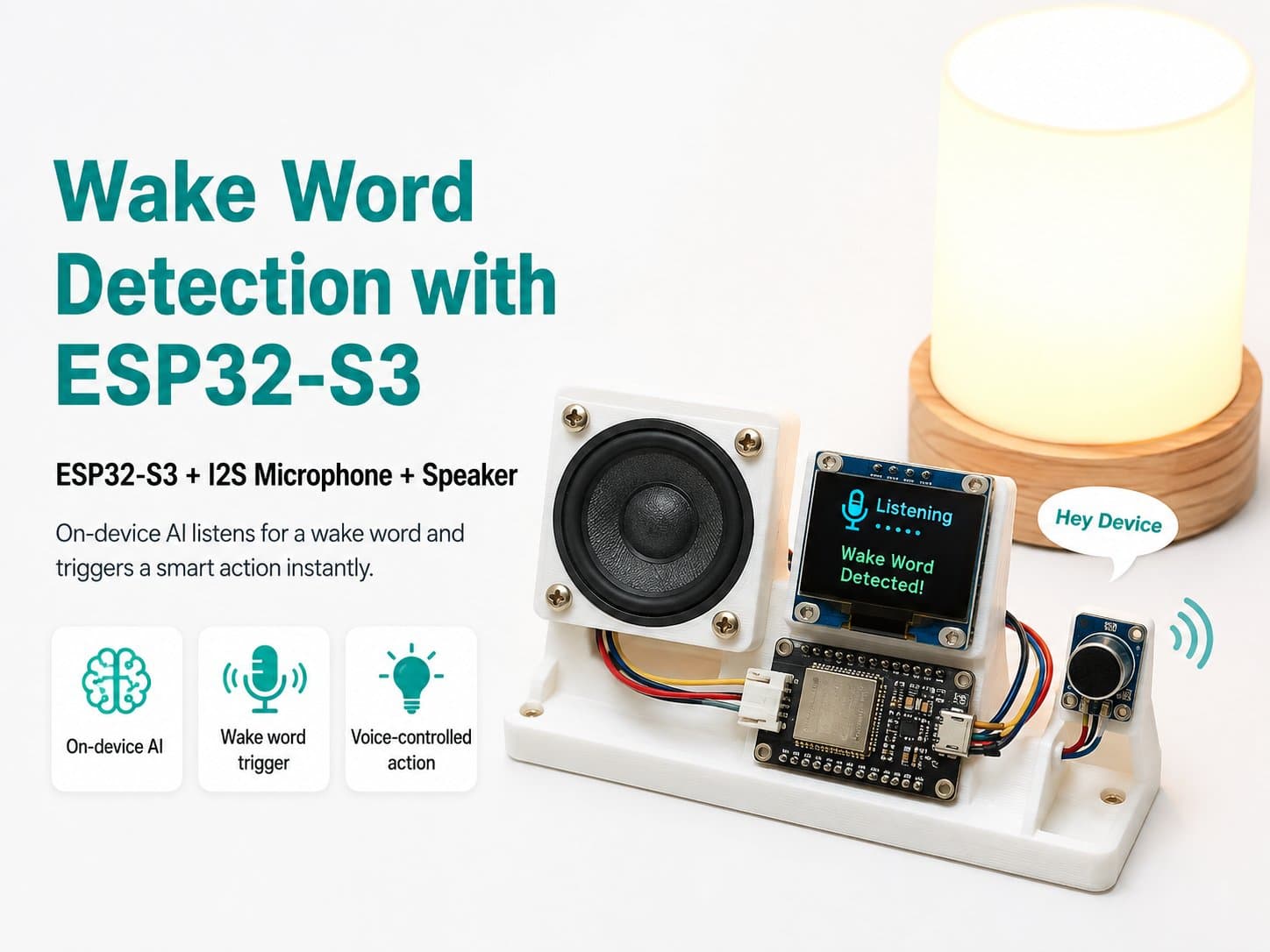
Components Needed for Wake Word Detection with ESP32-S3
The ESP32-S3-based Wake Word Detection project requires a few specific components for it to work effectively. Below is the list of required components with a technical explanation of each.
1. ESP32-S3
The ESP32-S3 is a powerful microcontroller with AI processing capability and WiFi/Bluetooth support. It runs at 3.3V and can clock up to 240 MHz. This microcontroller supports many connectivity protocols and handles audio processing well for a Wake Word Detection project. Note that only ESP32-S3 models with PSRAM have enough memory to run WakeNet/ESP-SR effectively.
2. INMP441 I2S Microphone
The INMP441 is a digital microphone using the I2S protocol, allowing high-quality audio signal transfer. It requires a 3.3V supply and has a maximum sample rate of up to 48 kHz. The I2S protocol ensures fast, accurate audio data transfer.
3. Power Circuit
The power circuit needs to supply a stable voltage to the ESP32-S3 and the INMP441 microphone. A 5V source can be converted to 3.3V using a voltage regulator. Make sure the current supplied is enough for all components to run simultaneously.
4. Development Board
A development board (such as a breadboard) makes it easy to connect components together without soldering. It's a handy tool for prototyping and developing the project.
5. Connecting Wires
Wires are needed to connect the components together. Use good-quality wires to ensure a stable signal between components.
Warning: make sure the connections between components are correct to avoid damaging the device.
6. Programming Software
To program the ESP32-S3, you need to use the ESP-IDF, since WakeNet and ESP-SR only support the ESP-IDF, not the Arduino IDE. If you want to use Arduino, you'll need a different solution or switch to the ESP-IDF.
To integrate WakeNet via ESP-SR in the ESP-IDF, you need to install and configure it correctly. Using ESP-IDF >= v4.4 and ESP-SR >= v1.5.2 is recommended.
Connecting the I2S Pins Between the ESP32-S3 and the INMP441:
WS (Word Select) — connect to the matching GPIO pin on the ESP32-S3
SD (Serial Data) — connect to the matching GPIO pin on the ESP32-S3
SCK (Serial Clock) — connect to the matching GPIO pin on the ESP32-S3
GND — connect to a GND pin on the ESP32-S3
VCC — supply 3.3V to the INMP441