Auto-Connecting Modules (Auto Wire)
Requirement: the diagram already has at least 1 module (besides the board).
Steps
- On the toolbar above the canvas, click "Auto-Connect Modules".
- The "Auto-Connect Modules" modal opens, and the "Modules on Diagram (N)" section lists each module along with its bus type label (I2C/SPI/UART) if applicable — modules that don't belong to these buses have an empty bus column.
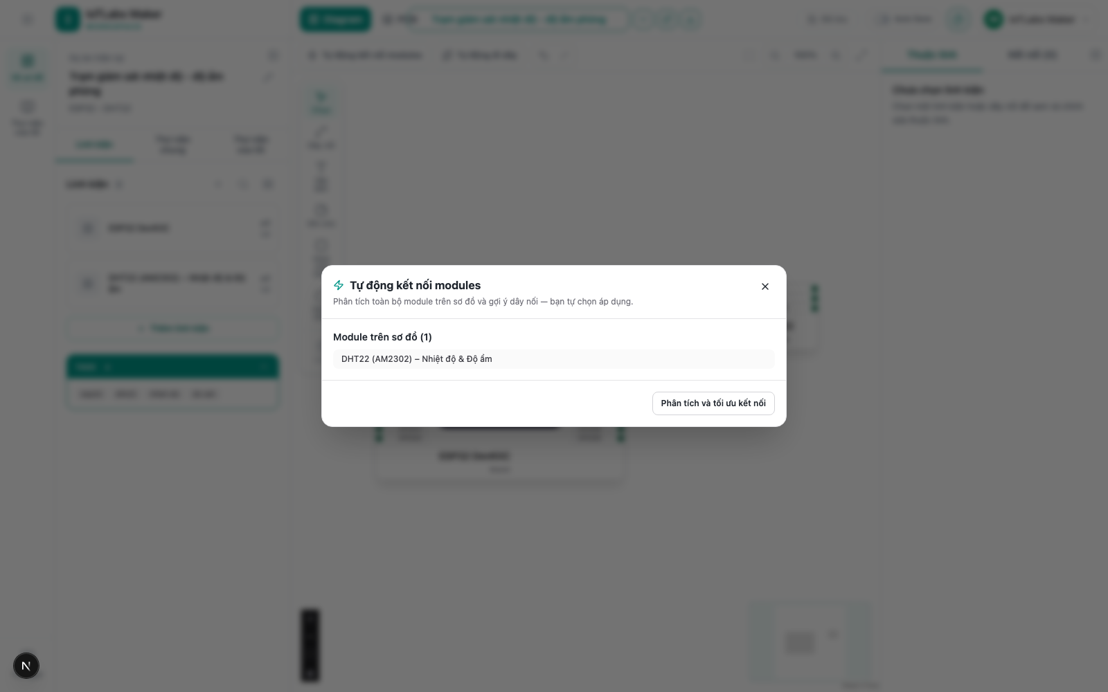
- Click "Analyze and Optimize Connections". A progress bar and log appear, showing lines like "Checking <module name>...", ending with "Done".
- After the analysis finishes, the "Connection Suggestions (N)" section lists each module that isn't connected yet (or is still missing wires), along with the number of wires that will be created and the bus type (with an "AI" label added if that suggestion was inferred with AI assistance for pins whose role wasn't clear).
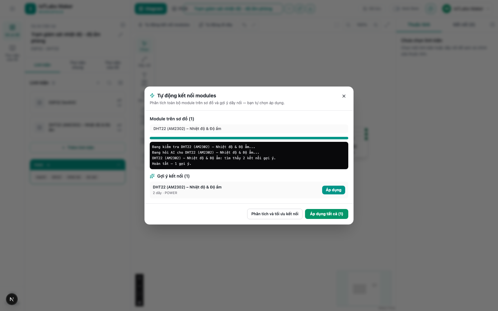
- Click "Apply" on an individual suggestion to apply only that module, or click "Apply All (N)" at the bottom of the modal to apply every suggestion at once.
- Click "Close" (the X icon in the top-right corner) to exit the modal.
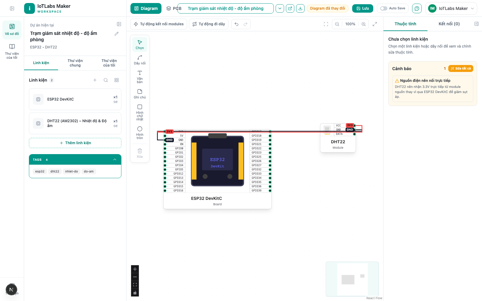
Result: the applied suggestions' wires are automatically drawn onto the diagram; existing wires and components (including wires you drew by hand) are preserved, and component positions are not shifted. If every module is already fully connected, the modal shows the message "No new suggestions — all modules are already connected."
Note
Re-analyzing multiple times is safe — a module whose suggestion has already been applied will not be suggested again (idempotent), and AI is not called again for pins that were already identified previously.
Example
For the "Room Temperature & Humidity Monitoring Station" diagram (ESP32 + DHT22, not yet wired): click "Auto-Connect Modules" → "Analyze and Optimize Connections" → the system recognizes the DHT22 needs 3.3V power, GND, and 1 DATA (digital) pin, and immediately suggests the 3 corresponding wires, one of which was inferred by AI (labeled "AI") because the DATA pin didn't directly match a standard name in the pin table. Click "Apply All" and you're done — no need to look up each pin in the datasheet yourself.