Adding Components to the Diagram
There are 2 ways: drag and drop from the left panel, or open the full library and click to add.
Method 1 — drag and drop from the left panel
- In the left panel, choose the "Shared Library" tab (commonly used, admin-approved components) or "My Library" (modules you created yourself).
- Type a keyword into the "Search hardware..." field to filter — the result groups are collapsed by default, click a group (e.g. the "Modules (1)" button) to expand it.
- Press and hold the left mouse button on a component card (the cursor shows "Drag to canvas") for about half a second, then drag it onto the canvas area and release at the position you want.
Method 2 — open the full library
- In the "Shared Library" tab, click the "Open Full Library" button to open the "Hardware Catalog" modal.
- Choose the source "Shared Library" or "My Library", then type a keyword into the "Search hardware..." field.
- Select a component, then click "Add to Diagram".
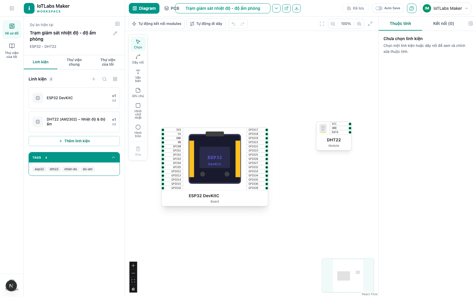
Result: the component appears as a node on the canvas; the status at the top of the page changes to "Diagram Changed" and the "Save" button becomes enabled.
Notes
- "Shared Library" only shows components that have been approved by an admin (
reviewed: true) — unapproved components and other people's private modules will not appear here. - "My Library" only shows modules you created yourself, entirely separate from "Shared Library".
- When you select a node already placed on the canvas, the Properties panel shows a scope label ("Shared Library" or "Private Library") matching that component's origin.
Example
For the "Room Temperature & Humidity Monitoring Station" project: search for "ESP32" in "Shared Library", drag an ESP32 DevKitC onto the canvas as the main board, then search for "DHT22" and drag a DHT22 (AM2302) sensor next to the board — as shown above, both components are now on the canvas but not yet wired, ready for the next step.