Detailed guide
Part 2: System Architecture and Wiring Diagram
Covers the data architecture, pin connection table, and how to protect the ESP32's ADC pins when using analog sensors.
Updated 31/08/2026
Part 2: System Architecture and Wiring Diagram
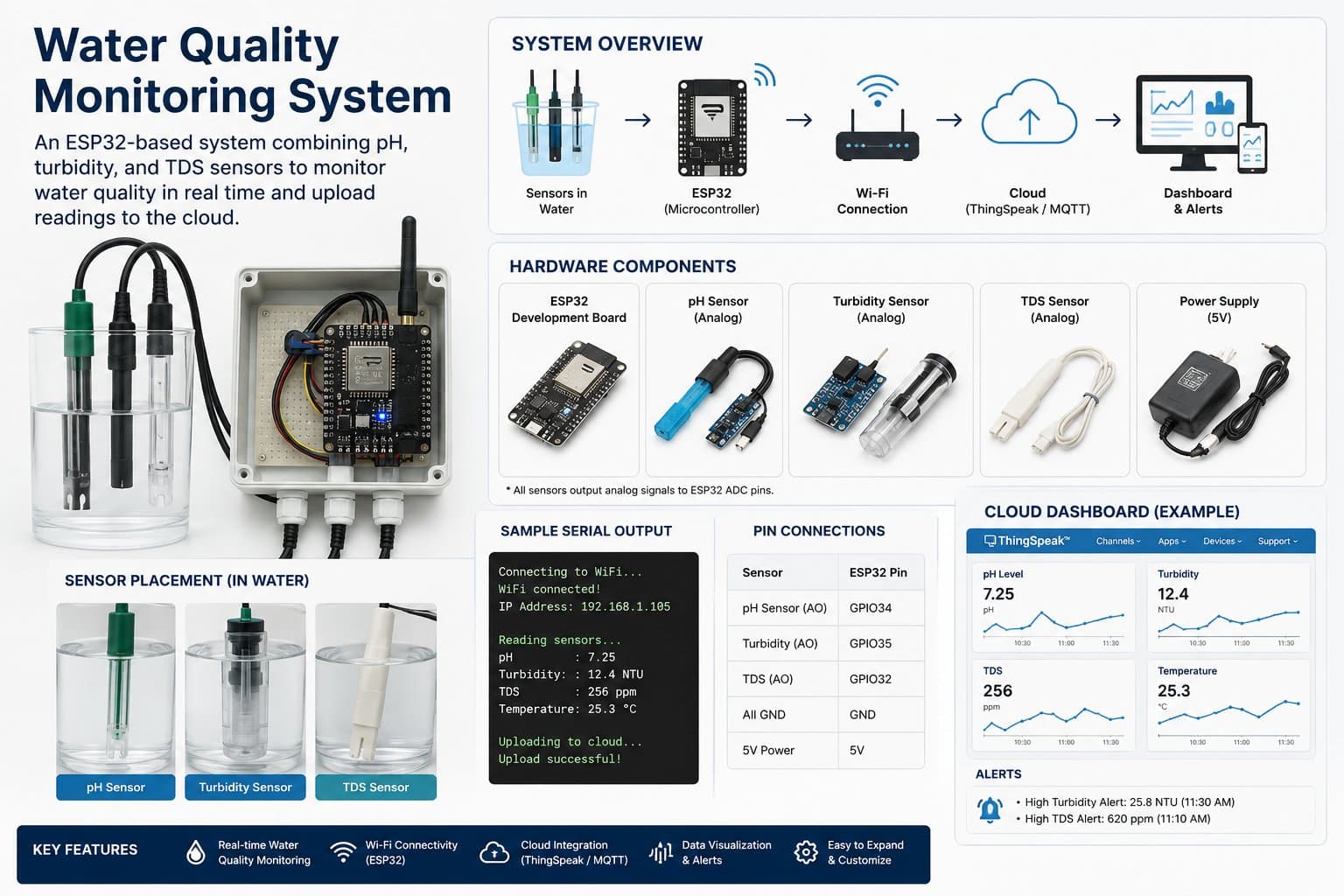
The system has three main blocks: water sensors, the ESP32 processing data, and the display/alert/cloud block.
[Water Sensors]
  ├── DS18B20 Temperature Sensor
  ├── TDS Sensor
  ├── pH Sensor
  └── Turbidity Sensor
        │
        ▼
[ESP32]
  ├── Read sensor data
  ├── Filter noise
  ├── Compute measured values
  ├── Evaluate water status
  └── Send via Serial / MQTT / Dashboard
        │
        ▼
[Output]
  ├── Serial Monitor
  ├── LED / Buzzer
  ├── OLED Display
  └── MQTT Dashboard
2.1. Full Pin Connection Table
| Device | Device Pin | ESP32 | Note |
|---|---|---|---|
| DS18B20 | DATA | GPIO4 | Needs a 4.7kΩ pull-up resistor. |
| TDS Sensor | AO | GPIO34 | ADC1, input-only. |
| pH Sensor | AO | GPIO35 | ADC1, input-only. |
| Turbidity Sensor | AO | GPIO32 | Needs a voltage divider if the output exceeds 3.3V. |
| Green LED | Anode | GPIO26 | Indicates NORMAL status. |
| Red LED | Anode | GPIO27 | Indicates WARNING/DANGER. |
| Buzzer | IN | GPIO25 | Activates on DANGER or SENSOR_ERROR. |
2.2. Connecting the DS18B20
The DS18B20 uses the 1-Wire interface. Its DATA pin needs a 4.7kΩ pull-up resistor to 3.3V.
3.3V ----[4.7kΩ]---- DATA DS18B20
                    │
GPIO4 --------------┘
GND ---------------- GND DS18B20
2.3. Protecting the ESP32's ADC Pins
The ESP32 should only receive an analog signal up to about 3.3V. If the turbidity or pH module outputs higher, use a voltage divider.
AO Sensor ---- R1 10kΩ ----+---- GPIO32 ESP32
                           |
                         R2 20kΩ
                           |
                          GND
Voltage divider formula:
Vout = Vin × R2 / (R1 + R2)With R1 = 10kΩ and R2 = 20kΩ, the ESP32 receives about 66.7% of the sensor's original voltage.