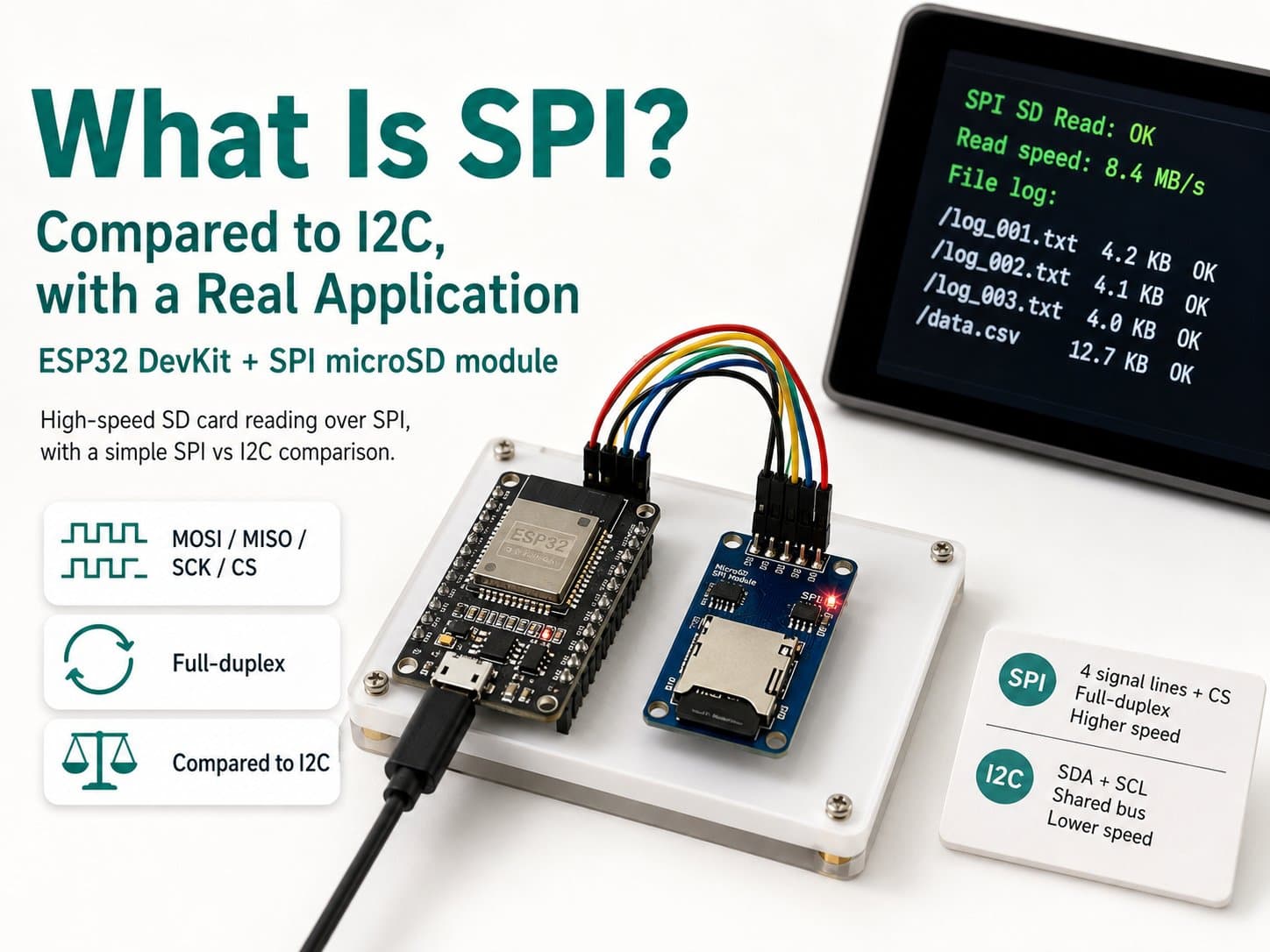
What Is SPI? Compared to I2C, with a Real Application
SPI principles (SCK/MOSI/MISO/CS), compared to I2C on speed and device addressing, with a hands-on example drawing to a 240x320 ILI9341 TFT display over SPI with an ESP32 DevKit.
SPI (Serial Peripheral Interface) is a synchronous serial communication protocol developed by Motorola, using a minimum of 4 wires: SCK (clock), MOSI (Master Out Slave In), MISO (Master In Slave Out), and CS/SS (Chip Select) — each slave device needs its own dedicated CS pin instead of an address like I2C.
In exchange, SPI has no low standardized speed ceiling like I2C: real-world speeds typically reach a few MHz up to tens of MHz, well suited for devices needing high bandwidth, like TFT displays.
This lesson uses a 2.4" 240x320 TFT display (ILI9341 driver) over SPI with an ESP32 DevKit, while directly comparing it with the I2C covered in the previous lesson.
Detailed guide
SPI principles (SCK/MOSI/MISO/CS) compared to I2C on speed and wire count, with a hands-on example drawing to a 240x320 ILI9341 TFT over SPI with an ESP32.
1. Introduction
SPI (Serial Peripheral Interface) is a full-duplex serial protocol (transmitting and receiving simultaneously) using 4 signal wires: SCK (Serial Clock, driven by the master), MOSI (Master Out Slave In), MISO (Master In Slave Out), and CS/SS (Chip Select, for device selection).
Unlike I2C, which uses addresses to distinguish devices on the same 2 wires, SPI uses a dedicated physical CS pin per device — to talk to a specific device, the master pulls that device's CS pin low before transmitting.
Trade-off: SPI needs more wires than I2C when there are multiple devices (each device adds a CS pin, while I2C stays at just 2 shared SDA/SCL wires), but in exchange it's much faster — SPI has no low standardized speed cap like I2C (100kHz/400kHz Standard/Fast-mode); in practice, many ICs/displays run at 10-40MHz.
This is why devices needing high bandwidth — TFT displays, SD cards, fast-sampling sensors — almost always use SPI rather than I2C.
2. Components Needed
| Component | Qty | Note |
|---|---|---|
| ESP32 DevKit V4 | 1 | Main board, acts as the SPI master |
| TFT 2.4" 240x320 SPI (ILI9341) | 1 | 65K-color display, Adafruit_ILI9341 library |
| Jumper wires | 8 | VCC, GND, CLK, MOSI, MISO, CS, DC, RST |
3. Wiring Diagram
| TFT ILI9341 | ESP32 |
|---|---|
| VCC | 3V3 |
| GND | GND |
| CLK / SCK | GPIO18 (VSPI SCK) |
| MOSI / SDA | GPIO23 (VSPI MOSI) |
| MISO | GPIO19 (VSPI MISO) |
| CS | GPIO5 |
| DC | GPIO27 |
| RST | GPIO33 |
| BL (Backlight) | 3V3 (always on) |
Compared to the I2C diagram in the previous lesson (only 2 shared signal wires, SDA/SCL, for every device), SPI here needs 5 dedicated signal wires (CLK, MOSI, MISO, CS, DC — with RST also counting as a control line). If you add a second SPI display, CLK/MOSI/MISO can be shared, but CS must be an entirely different GPIO pin.
4. Example #1 — Basic Drawing to the TFT over SPI
A sketch that initializes Adafruit_ILI9341 with CS=GPIO5, DC=GPIO27, RST=GPIO33 (the default VSPI bus: SCK=18, MOSI=23, MISO=19 need no explicit declaration), prints text, and draws a rectangle that changes color every 1.5 seconds to illustrate SPI's continuous writes with no address needed before each command.
/*
  What Is SPI? — Example #1: Basic Drawing to an ILI9341 TFT over SPI
  Board: ESP32 DevKit V4 + TFT 2.4" 240x320 SPI (ILI9341)

  SPI pins (ESP32 default VSPI): CLK=GPIO18, MOSI=GPIO23, MISO=GPIO19
  The display's own control pins: CS=GPIO5, DC=GPIO27, RST=GPIO33
  The backlight (BL) is wired directly to 3V3 (always on).

  Compared to I2C (2 shared SDA/SCL wires for multiple devices, typically
  100kHz-400kHz), SPI uses more wires (SCK, MOSI, MISO, plus a dedicated
  CS per device) but runs much faster (a few MHz to tens of MHz), suited
  for displays that need a fast refresh.
*/

#include <SPI.h>
#include <Adafruit_GFX.h>
#include <Adafruit_ILI9341.h>

#define TFT_CS 5
#define TFT_DC 27
#define TFT_RST 33

Adafruit_ILI9341 tft = Adafruit_ILI9341(TFT_CS, TFT_DC, TFT_RST);

void setup() {
  Serial.begin(115200);
  delay(300);
  Serial.println(F("=== SPI TFT ILI9341 demo boot ==="));

  tft.begin(); // SPI mac dinh: SCK=18, MOSI=23, MISO=19 (VSPI)
  tft.setRotation(1);
  tft.fillScreen(ILI9341_BLACK);

  tft.setCursor(10, 10);
  tft.setTextColor(ILI9341_WHITE);
  tft.setTextSize(2);
  tft.println("SPI Demo");

  tft.setTextSize(1);
  tft.setCursor(10, 40);
  tft.println("CLK=18 MOSI=23 MISO=19");
  tft.setCursor(10, 55);
  tft.println("CS=5 DC=27 RST=33");

  Serial.println(F("Da khoi tao TFT qua SPI"));
}

void loop() {
  static uint16_t colors[] = {ILI9341_RED, ILI9341_GREEN, ILI9341_BLUE, ILI9341_YELLOW};
  static uint8_t idx = 0;
  static unsigned long last = 0;

  if (millis() - last >= 1500) {
    last = millis();
    tft.fillRect(10, 80, 100, 30, colors[idx]);
    Serial.printf("Ve hinh chu nhat mau #%u (SPI ghi lien tuc, khong can dia chi)\n", idx);
    idx = (idx + 1) % 4;
  }
}
5. Example #2 — The Real Application: a Seconds-Counter Clock
A second variant that takes advantage of SPI's high write speed to update a running-seconds counter on the display every second without stutter, illustrating a real-world case where SPI outperforms I2C when continuously redrawing a large area.
/*
  What Is SPI? — Example #2: The Real Application — a Seconds-Counter Clock on the TFT
  Board: ESP32 DevKit V4 + TFT 2.4" 240x320 SPI (ILI9341)
  Same pin wiring as example #1: CLK=18, MOSI=23, MISO=19, CS=5, DC=27, RST=33.
*/

#include <SPI.h>
#include <Adafruit_GFX.h>
#include <Adafruit_ILI9341.h>

#define TFT_CS 5
#define TFT_DC 27
#define TFT_RST 33

Adafruit_ILI9341 tft = Adafruit_ILI9341(TFT_CS, TFT_DC, TFT_RST);

unsigned long bootMillis = 0;

void setup() {
  Serial.begin(115200);
  delay(300);
  Serial.println(F("=== TFT dong ho dem giay (SPI) ==="));

  tft.begin();
  tft.setRotation(1);
  tft.fillScreen(ILI9341_BLACK);
  tft.setTextColor(ILI9341_GREEN, ILI9341_BLACK);
  tft.setTextSize(4);

  bootMillis = millis();
}

void loop() {
  unsigned long secs = (millis() - bootMillis) / 1000UL;

  tft.setCursor(40, 100);
  tft.printf("%6lus", secs); // ghi de tren cung vi tri, tan dung toc do SPI cao

  Serial.printf("Uptime: %lus (cap nhat qua SPI moi vong lap)\n", secs);

  delay(1000);
}
6. Direct Comparison: I2C vs SPI
| Criterion | I2C | SPI |
|---|---|---|
| Signal wire count | 2 (SDA, SCL) shared by every device | 4 base wires (SCK, MOSI, MISO, CS) + 1 dedicated CS per device |
| How a device is selected | A 7-bit address sent in the data frame | A physical CS pin pulled low |
| Typical speed | 100kHz–400kHz (a faster Fast/High-speed standard exists, but few modules support it) | A few MHz to tens of MHz |
| Duplex | Half-duplex (shares one data wire) | Full-duplex (independent MOSI/MISO) |
| Best suited for | Small sensors, little data, saving pins | Displays, memory cards, devices needing high bandwidth |
7. Common Issues
| Issue | Cause | Fix |
|---|---|---|
| The display is blank/shows nothing | Mixed-up DC/RST pins, or CS pointing to the wrong GPIO | Double-check the parameter order in Adafruit_ILI9341(CS, DC, RST) |
| The image is noisy/colors bleed | Wires too long for the high SPI speed, or a missing shared GND | Shorten the MOSI/SCK wires, make sure GND is solidly connected |
| Compile error, missing library | Adafruit_ILI9341/Adafruit_GFX aren't installed | arduino-cli lib install "Adafruit ILI9341" "Adafruit GFX Library" |
| Adding a second SPI display causes conflicts | Reusing the same CS pin as the first device | Every SPI device must have its own unique CS GPIO pin, never shared |
8. Summary
SPI trades more wires than I2C (especially with multiple devices) for much higher speed — with no low standardized cap like I2C's 100/400kHz. For devices that need to continuously transfer large amounts of data (displays, memory cards), SPI is almost always the required choice; for small, low-data sensors where saving GPIO pins matters, I2C remains the more economical option.