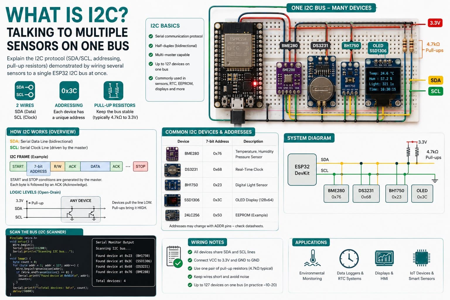
What Is I2C? Talking to Multiple Sensors on One Bus
Learn the I2C protocol (SDA/SCL, 7-bit addressing, ACK/NACK) through a hands-on example: pairing a BMP280 (0x76) and an SSD1306 OLED (0x3C) on the same 2 wires with an ESP32 DevKit.
I2C (Inter-Integrated Circuit) is a 2-wire serial communication protocol (SDA - data, SCL - clock) that lets multiple devices (master/slave) share a single bus. Each slave device is identified by a unique 7-bit address, letting a single ESP32 board read many sensors/displays at once using just 2 signal wires (plus power/ground).
This lesson uses a BMP280 (address 0x76) and an SSD1306 OLED (address 0x3C) on the same GPIO21 (SDA) / GPIO22 (SCL) bus on an ESP32 DevKit to demonstrate the address-based bus-sharing mechanism.
Detailed guide
I2C principles, how multiple devices share 2 SDA/SCL wires via 7-bit addressing, with a hands-on example pairing a BMP280 + SSD1306 OLED on an ESP32.
1. Introduction
I2C (Inter-Integrated Circuit, developed by Philips/NXP) is a synchronous serial protocol using 2 signal wires: SDA (Serial Data) for data, and SCL (Serial Clock) for the clock signal generated by the master (here, the ESP32). Both wires are open-drain, so a pull-up resistor (typically 4.7kΩ) to the supply rail is mandatory — most cheap sensor/display modules already include this resistor onboard.
I2C's strength is that multiple devices (multi-drop) can share exactly the same 2 SDA/SCL wires. The master distinguishes each device by a 7-bit address (0x08–0x77) sent right after the START bit.
Whichever device matches that address responds with an ACK bit (pulling SDA low); if no device answers, the master reads a NACK and knows the bus is "silent" at that address. This lesson pairs a BMP280 (default address 0x76, changeable to 0x77 via the SDO pin) and an SSD1306 OLED display (fixed address 0x3C) on the same GPIO21 (SDA) / GPIO22 (SCL) wires on an ESP32 DevKit to prove: with just 2 wires, the ESP32 can still read both devices separately thanks to their different addresses.
2. Components Needed
| Component | Qty | Note |
|---|---|---|
| ESP32 DevKit V4 | 1 | Main board, acts as the I2C master |
| BMP280 (pressure/temperature, I2C) | 1 | Address 0x76 (default) or 0x77 |
| 0.96" 128x64 I2C OLED (SSD1306) | 1 | Address 0x3C |
| Jumper wires | 4-6 | SDA, SCL, VCC, GND for each module |
3. Wiring Diagram
| BMP280 | ESP32 |
|---|---|
| VCC | 3V3 |
| GND | GND |
| SCL | GPIO22 |
| SDA | GPIO21 |
| OLED SSD1306 | ESP32 |
|---|---|
| VCC | 3V3 |
| GND | GND |
| SCL | GPIO22 (shared wire with the BMP280) |
| SDA | GPIO21 (shared wire with the BMP280) |
Note: both modules' SDA and SCL connect in parallel to the same GPIO21/GPIO22 wires — this is the key difference from SPI, where every device needs its own CS pin. See the project's Workspace Diagram / Connections tab for the full diagram with exact pin positions.
4. Example #1 — Scanning the Bus and Reading Both Devices
A sketch that uses Wire.begin(21, 22), scans the full address range 1–126 to print which devices ACK, then initializes both Adafruit_BMP280 (0x76) and Adafruit_SSD1306 (0x3C) and reads/displays data every 2 seconds.
/*
  What Is I2C? — Example #1: Scanning the Bus and Reading Two Devices
  Board: ESP32 DevKit V4
  Devices on the same I2C bus (SDA=GPIO21, SCL=GPIO22):
    - BMP280 (pressure/temperature)  -> address 0x76 (SDO tied to GND) or 0x77 (SDO tied to VCC)
    - OLED SSD1306 128x64            -> address 0x3C

  Demonstrated idea: multiple devices can share the same 2 SDA/SCL wires
  because each is distinguished by a unique 7-bit I2C address.
*/

#include <Wire.h>
#include <Adafruit_BMP280.h>
#include <Adafruit_GFX.h>
#include <Adafruit_SSD1306.h>

#define SDA_PIN 21
#define SCL_PIN 22

#define OLED_ADDR 0x3C
#define BMP280_ADDR 0x76

Adafruit_BMP280 bmp;
Adafruit_SSD1306 display(128, 64, &Wire, -1);

bool bmpReady = false;
bool oledReady = false;

void scanBus() {
  Serial.println(F("Quet dia chi I2C tren bus..."));
  uint8_t found = 0;
  for (uint8_t addr = 1; addr < 127; addr++) {
    Wire.beginTransmission(addr);
    uint8_t err = Wire.endTransmission();
    if (err == 0) {
      Serial.printf("  -> Tim thay thiet bi tai 0x%02X\n", addr);
      found++;
    }
  }
  Serial.printf("Tong: %u thiet bi\n", found);
}

void setup() {
  Serial.begin(115200);
  delay(300);
  Serial.println(F("=== I2C multi-device demo boot ==="));

  Wire.begin(SDA_PIN, SCL_PIN);
  Wire.setClock(100000); // 100kHz Standard-mode, an toan cho day breadboard dai

  scanBus();

  oledReady = display.begin(SSD1306_SWITCHCAPVCC, OLED_ADDR);
  if (!oledReady) {
    Serial.println(F("[WARN] Khong tim thay OLED tai 0x3C"));
  } else {
    display.clearDisplay();
    display.setTextSize(1);
    display.setTextColor(SSD1306_WHITE);
    display.setCursor(0, 0);
    display.println(F("I2C multi-device"));
    display.display();
  }

  bmpReady = bmp.begin(BMP280_ADDR);
  if (!bmpReady) {
    Serial.println(F("[WARN] Khong tim thay BMP280 tai 0x76 (thu 0x77?)"));
  }
}

void loop() {
  static unsigned long lastRead = 0;
  if (millis() - lastRead >= 2000) {
    lastRead = millis();

    float tempC = bmpReady ? bmp.readTemperature() : NAN;
    float pressHpa = bmpReady ? bmp.readPressure() / 100.0F : NAN;

    if (bmpReady) {
      Serial.printf("BMP280 (0x76): temp=%.2fC pressure=%.2fhPa\n", tempC, pressHpa);
    } else {
      Serial.println(F("BMP280 (0x76): khong co du lieu"));
    }

    if (oledReady) {
      display.clearDisplay();
      display.setCursor(0, 0);
      display.println(F("I2C: BMP280 + OLED"));
      display.setCursor(0, 16);
      if (bmpReady) {
        display.printf("T: %.1f C\n", tempC);
        display.printf("P: %.1f hPa\n", pressHpa);
      } else {
        display.println(F("BMP280: N/A"));
      }
      display.setCursor(0, 48);
      display.println(F("addr 0x76 / 0x3C"));
      display.display();
    }
  }
}
5. Example #2 — The Real Application: a Pressure/Temperature Display Station
A second variant that skips manual scanning, initializing both devices directly at their known addresses and showing temperature, pressure, and estimated altitude (calculated from a sea-level reference pressure of 1013.25 hPa) directly on the OLED.
/*
  What Is I2C? — Example #2: The Real Application — a Pressure/Temperature Display Station
  Board: ESP32 DevKit V4 + BMP280 (0x76) + OLED SSD1306 (0x3C) on the same I2C bus.
  Doesn't need Serial to operate — all data is shown directly on the OLED,
  demonstrating the real-world use of sharing one bus across multiple sensors.
*/

#include <Wire.h>
#include <Adafruit_BMP280.h>
#include <Adafruit_GFX.h>
#include <Adafruit_SSD1306.h>

#define SDA_PIN 21
#define SCL_PIN 22
#define OLED_ADDR 0x3C
#define BMP280_ADDR 0x76

Adafruit_BMP280 bmp;
Adafruit_SSD1306 display(128, 64, &Wire, -1);

void setup() {
  Serial.begin(115200);
  delay(300);
  Serial.println(F("=== Tram hien thi ap suat/nhiet do (I2C shared bus) ==="));

  Wire.begin(SDA_PIN, SCL_PIN);
  Wire.setClock(100000);

  if (!display.begin(SSD1306_SWITCHCAPVCC, OLED_ADDR)) {
    Serial.println(F("[ERROR] OLED khong phan hoi tai 0x3C"));
  }
  if (!bmp.begin(BMP280_ADDR)) {
    Serial.println(F("[ERROR] BMP280 khong phan hoi tai 0x76"));
  }

  display.clearDisplay();
  display.setTextSize(1);
  display.setTextColor(SSD1306_WHITE);
  display.setCursor(0, 0);
  display.println(F("Khoi dong tram do..."));
  display.display();
}

void loop() {
  float tempC = bmp.readTemperature();
  float pressHpa = bmp.readPressure() / 100.0F;
  float altitude = bmp.readAltitude(1013.25F); // ap suat quy chieu muc nuoc bien

  display.clearDisplay();
  display.setTextSize(1);
  display.setCursor(0, 0);
  display.println(F("TRAM DO AP SUAT"));
  display.drawLine(0, 10, 127, 10, SSD1306_WHITE);

  display.setTextSize(2);
  display.setCursor(0, 16);
  display.printf("%.1fC\n", tempC);

  display.setTextSize(1);
  display.setCursor(0, 40);
  display.printf("Ap suat: %.1f hPa\n", pressHpa);
  display.setCursor(0, 52);
  display.printf("Do cao ~%.0f m\n", altitude);

  display.display();

  delay(1000);
}
6. Real Applications & Extensions
Because I2C uses addresses to distinguish devices, a single ESP32 I2C bus (the default Wire bus, or Wire1 for a second bus) can host dozens of different sensors/displays as long as no two share an address. Some ICs let you change their address via a hardware configuration pin (e.g. the BMP280's 0x76/0x77 via its SDO pin) — useful when you need two identical modules on the same bus.
Real applications: mini weather stations, multi-channel sensor dashboards, and I2C I/O-expander modules (PCF8574, MCP23017) all rely on exactly this addressing mechanism.
7. Common Issues
| Issue | Cause | Fix |
|---|---|---|
| Scanning the bus finds no devices | Missing pull-up resistors, or SDA/SCL are swapped | Check whether the module already has pull-ups; swap SDA↔SCL |
| The BMP280 doesn't respond at 0x76 | The module is set to address 0x77 (SDO tied to VCC) | Try again with bmp.begin(0x77) or check the SDO pin |
| The OLED and BMP280 "fight", data comes out wrong | Both devices share the same I2C address (rare for this pair, but common when adding a third identical module) | Change one module's address via its configuration pin, or use a second I2C bus (Wire1) |
| Data gets noisy over a long wire run | I2C's 400kHz speed is too high for a long breadboard wire | Drop to 100kHz with Wire.setClock(100000) |
8. Summary
I2C solves the "many devices, few wires" problem by addressing each device individually on the same 2 SDA/SCL wires.
The trade-off is lower speed than SPI (typically 100kHz-400kHz versus SPI's several MHz) and the need to manage addresses to avoid collisions. It's the default choice for small sensors/displays with light data needs where saving ESP32 GPIO pins matters.