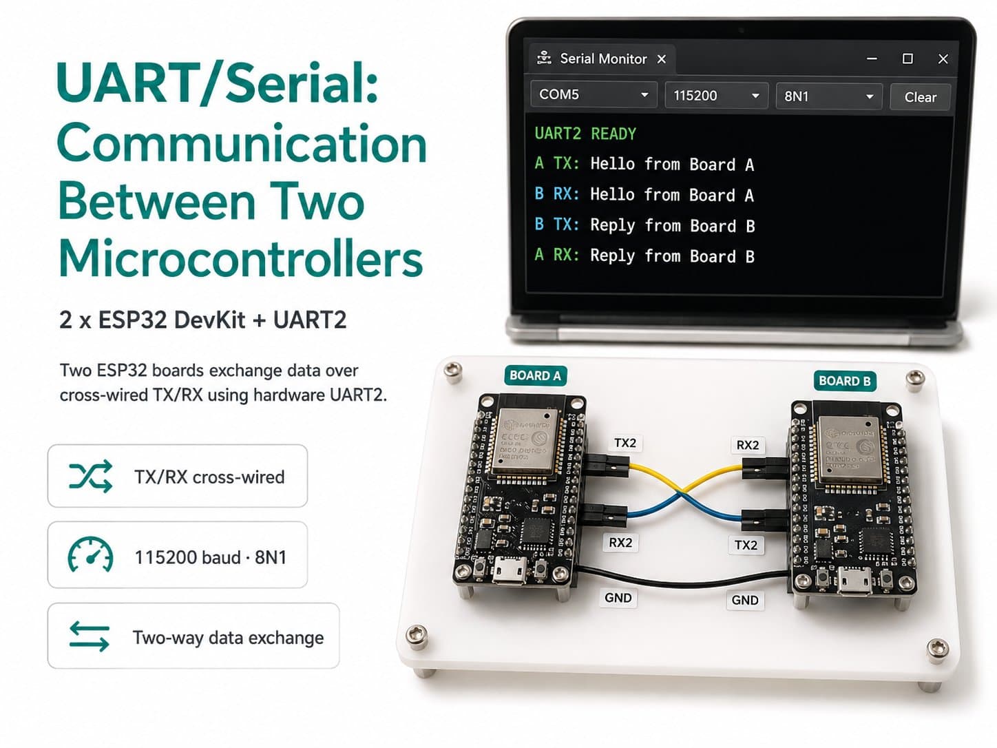
UART/Serial: Communication Between Two Microcontrollers
UART/Serial principles (TX/RX, baud rate, the 8N1 frame) through a hands-on example: two ESP32 DevKit boards exchanging data over hardware UART2 with cross-wired TX-RX.
UART (Universal Asynchronous Receiver-Transmitter) is an asynchronous serial communication method — there's no dedicated clock wire like I2C/SPI; both sides stay in sync only by agreeing beforehand on a baud rate (e.g. 115200 bits/second) and a data frame format (8 data bits, no parity, 1 stop bit — abbreviated 8N1).
Communication needs just 2 signal wires: TX (Transmit) and RX (Receive), which must always be cross-wired — one side's TX goes to the other side's RX.
This lesson uses the ESP32's hardware UART2 (leaving UART0 free, since it's busy serving the Serial Monitor over USB) so two ESP32 DevKit boards can exchange data directly with each other, with no WiFi/Bluetooth involved.
Detailed guide
UART principles (TX/RX, baud rate, the 8N1 frame), demonstrated with two ESP32 boards exchanging data over hardware UART2 with cross-wired TX-RX.
1. Introduction
UART (Universal Asynchronous Receiver-Transmitter) is an asynchronous serial communication method: there's no dedicated clock wire, and both devices track timing on their own using an agreed-upon baud rate (e.g. 115200 bits/second) to know when to sample each bit.
The most common UART frame format is 8N1: 1 start bit, 8 data bits, no parity bit, 1 stop bit. Two-way communication needs only 2 signal wires, TX (Transmit) and RX (Receive), but they must be cross-wired: one device's TX pin connects to the other device's RX pin (never TX-TX or RX-RX).
The ESP32 has 3 independent hardware UARTs (UART0, UART1, UART2). UART0 is wired to the USB port by default to handle flashing and the Serial Monitor — using UART0 to talk to another board would conflict with debugging over the computer.
This lesson uses UART2 (default pins RX2=GPIO16, TX2=GPIO17 on the ESP32 DevKit) as a dedicated channel between the two boards, keeping UART0/Serial Monitor free for viewing debug logs over USB.
2. Components Needed
| Component | Qty | Note |
|---|---|---|
| ESP32 DevKit V4 (Board A) | 1 | Flash with "sample1" code — acts as the PING sender |
| ESP32 DevKit V4 (Board B) | 1 | Flash with "sample2" code — receives and echoes an ACK |
| Jumper wires | 3 | Cross-wired TX↔RX, shared GND |
3. Wiring Diagram
| Board A (ESP32) | Board B (ESP32) |
|---|---|
| TX2 / GPIO17 | RX2 / GPIO16 |
| RX2 / GPIO16 | TX2 / GPIO17 |
| GND | GND |
Important note: this wiring is crossed — Board A's TX must plug into Board B's RX, and vice versa. Both boards still keep their own USB cable for power + independently viewing their Serial Monitor (UART0); the UART2 wiring is used purely for the two boards to talk directly to each other.
4. Example #1 — Board A (Sends PING, Receives a Reply)
Board A uses HardwareSerial LinkSerial(2) to set up UART2 with begin(115200, SERIAL_8N1, 16, 17), sending a line PING:<counter>\n every second over TX2, while listening for Board B's reply on RX2 and printing it to the Serial Monitor (UART0/USB).
/*
  UART/Serial: Communication Between Two Microcontrollers — BOARD A (sends commands, receives replies)
  Board: ESP32 DevKit V4  #A  <-->  ESP32 DevKit V4 #B (sample "Board B")

  Uses hardware UART2 (leaving UART0 free, since it's busy with USB/Serial Monitor):
    Board A TX2 (GPIO17) --> Board B RX2 (GPIO16)
    Board A RX2 (GPIO16) <-- Board B TX2 (GPIO17)
    Board A GND          --- Board B GND   (mandatory: both boards must share a ground)

  Simple framing protocol: each line ends with '\n'.
  Board A acts as "master": sends a counter every second, waits for Board B to echo it back.
*/

HardwareSerial LinkSerial(2); // UART2

#define LINK_RX_PIN 16
#define LINK_TX_PIN 17

uint32_t counter = 0;
unsigned long lastSend = 0;

void setup() {
  Serial.begin(115200);       // UART0 -> USB, used only for debug/monitor
  delay(300);
  Serial.println(F("=== UART Board A boot ==="));

  LinkSerial.begin(115200, SERIAL_8N1, LINK_RX_PIN, LINK_TX_PIN);
  Serial.println(F("UART2 san sang: TX=GPIO17 RX=GPIO16 @115200 8N1"));
}

void loop() {
  // Gui 1 dong moi giay
  if (millis() - lastSend >= 1000) {
    lastSend = millis();
    counter++;
    LinkSerial.printf("PING:%lu\n", counter);
    Serial.printf("[A->B] PING:%lu\n", counter);
  }

  // Doc phan hoi tu Board B (neu co)
  static String rxBuf;
  while (LinkSerial.available()) {
    char c = (char)LinkSerial.read();
    if (c == '\n') {
      Serial.printf("[B->A] %s\n", rxBuf.c_str());
      rxBuf = "";
    } else if (c != '\r') {
      rxBuf += c;
    }
  }
}
5. Example #2 — Board B (Receives PING, Echoes an ACK)
Board B listens on UART2, and once it has received a full line ending in \n, it extracts the counter and sends back ACK:<counter>\n — demonstrating true two-way communication (not just one-way broadcasting).
/*
  UART/Serial: Communication Between Two Microcontrollers — BOARD B (receives commands, echoes a reply)
  Board: ESP32 DevKit V4 #B  <-->  ESP32 DevKit V4 #A (sample "Board A")

  Cross-wired TX<->RX between the two boards (mandatory for UART: one side's TX
  must go into the other side's RX, never TX-TX):
    Board B TX2 (GPIO17) --> Board A RX2 (GPIO16)
    Board B RX2 (GPIO16) <-- Board A TX2 (GPIO17)
    Board B GND          --- Board A GND
*/

HardwareSerial LinkSerial(2); // UART2

#define LINK_RX_PIN 16
#define LINK_TX_PIN 17

void setup() {
  Serial.begin(115200);
  delay(300);
  Serial.println(F("=== UART Board B boot ==="));

  LinkSerial.begin(115200, SERIAL_8N1, LINK_RX_PIN, LINK_TX_PIN);
  Serial.println(F("UART2 san sang: TX=GPIO17 RX=GPIO16 @115200 8N1"));
}

void loop() {
  static String rxBuf;
  while (LinkSerial.available()) {
    char c = (char)LinkSerial.read();
    if (c == '\n') {
      Serial.printf("[A->B] nhan: %s\n", rxBuf.c_str());

      // Tach so dem sau dau ':' va echo lai kem nhan "ACK"
      int sep = rxBuf.indexOf(':');
      String payload = (sep >= 0) ? rxBuf.substring(sep + 1) : rxBuf;
      LinkSerial.printf("ACK:%s\n", payload.c_str());
      Serial.printf("[B->A] gui: ACK:%s\n", payload.c_str());

      rxBuf = "";
    } else if (c != '\r') {
      rxBuf += c;
    }
  }
}
6. Real Applications & Extensions
Direct UART communication between two microcontrollers is typically used when: (1) one board handles real-time hardware tasks (reading an encoder, driving a high-speed motor) and sends a summary result to a main board that handles WiFi/logic; (2) GPS modules, SIM/4G modules, and industrial RS232/RS485 sensors all use UART as their native interface; (3) as a debug bridge between two systems with no other shared bus available. Since UART has no addressing like I2C and no CS pin like SPI, it only suits point-to-point connections between exactly 2 devices.
7. Common Issues
| Issue | Cause | Fix |
|---|---|---|
| Receiving nothing / garbage data | The baud rate doesn't match between the two sides | Make sure both boards use the exact same baud value (here, 115200) |
| No communication even though the wires are connected | TX-TX / RX-RX are wired instead of crossed | Swap it: one board's TX must go into the other board's RX |
| Data gets mixed up with debug logs | Mistakenly using UART0 (Serial) for both debugging and board-to-board communication | Keep them separate: Serial (UART0/USB) for debug only, LinkSerial (UART2) for board-to-board communication only |
| Both boards run without errors but show no response | Missing a shared GND connection between the two boards | Connecting GND-GND is mandatory so both UARTs share the same voltage reference |
8. Summary
UART is the simplest of the three protocols (I2C/SPI/UART): just 2 wires, no addressing or device-select pin needed, but in exchange it can only connect exactly 2 devices and requires both sides to agree on a baud rate beforehand.
It's the natural choice for a point-to-point link between two microcontrollers, or for talking to peripheral modules (GPS, SIM, RS232) that only support UART.