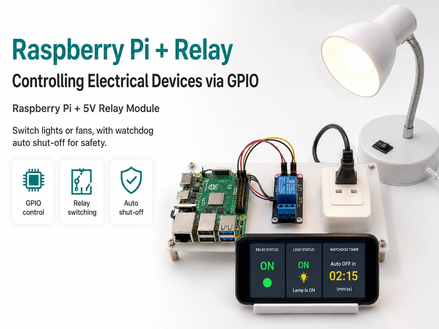
Raspberry Pi + Relay: Controlling Electrical Devices via GPIO
Use a 5V single-channel relay to switch electrical devices (lights, fans) on/off via Raspberry Pi's GPIO, with a safety watchdog that auto-shuts-off if left on too long.
The third GPIO intro project: using a single-channel relay module to switch an electrical device (light, fan, outlet) on and off with a digital signal from the Raspberry Pi.
You'll learn the active-low relay principle, how to control it safely, and how to build a control service with an automatic on/off schedule plus a watchdog mechanism that shuts things off automatically to prevent a device being left on "by accident" for too long — a mandatory safety requirement when switching real electrical loads.
Detailed guide
Learn to use a relay module with a Raspberry Pi to safely switch DC loads from GPIO, understand active-low logic, and build up to a watchdog-protected control service.
1. Introduction
A relay module is the most common way for a low-signal microcontroller (3.3V/5V, a few mA) to switch a much higher-power load — thanks to a mechanical switching mechanism (an electromagnetic coil pulling a contact closed) and an opto-isolator that protects the GPIO.
Common relay modules on the market are usually active-low: the IN pin at LOW (0V) closes (activates) the relay, and HIGH (3.3V/5V) opens (deactivates) it — the opposite of the usual "HIGH = on" intuition, which trips up a lot of beginners.
This lesson uses a 5V/12V DC load (a 12V LED light, a small DC fan, a 5V mini pump) as the standard so you can practice completely safely, with no risk of electric shock while first learning GPIO/relays.
2. Components Needed
| Component | Qty | Reference Price |
|---|---|---|
| Raspberry Pi 4 Model B (with Raspberry Pi OS installed) or another version | 1 | ~1,500,000₫ |
| 1-Channel 5V Relay Module (with opto-isolator) | 1 | ~20,000₫ |
| Jumper wires (male-female) | 3 | ~5,000₫ |
| A DC load for testing: a 12V LED light/12V LED strip, or a small DC fan (with its own separate 12V/5V power supply for the load) | 1 | ~30,000–50,000₫ |
3. Wiring Diagram
| Relay Module | Raspberry Pi 4 |
|---|---|
| VCC | 5V (Pin 2) |
| GND | GND |
| IN | GPIO18 (Pin 12) — active-low: LOW = relay closed (ON) |
| COM / NO | Wired in series on the positive (+) lead of the 12V/5V DC load, with the load's power coming from its own adapter — not from the RPi |
Safety: a 12V/5V DC load poses no shock risk, so it's fine to touch the wires while testing. Still power down the load before connecting/disconnecting wires to avoid small sparks or shorting the relay's contacts.
4. Example #1 — Basic Relay On/Off
Closes/opens the relay on a 3-second cycle to verify the connection works correctly, while also demonstrating the relay_on()/relay_off() helper functions that wrap the active-low logic.
#!/usr/bin/env python3
"""
Raspberry Pi + Relay 1 kenh - Dieu khien tai DC (den LED 12V, quat DC...) qua GPIO

Wiring:
  Relay VCC -> RPi 5V
  Relay GND -> RPi GND
  Relay IN  -> RPi GPIO18 (active-low: LOW = dong relay = BAT)
  Relay COM/NO -> day duong (+) cua tai DC, nguon tai lay tu adapter rieng
"""
import RPi.GPIO as GPIO
import time

RELAY_PIN = 18
ACTIVE_LOW = True  # module relay pho bien la active-low


def relay_on():
    GPIO.output(RELAY_PIN, GPIO.LOW if ACTIVE_LOW else GPIO.HIGH)


def relay_off():
    GPIO.output(RELAY_PIN, GPIO.HIGH if ACTIVE_LOW else GPIO.LOW)


def setup():
    GPIO.setmode(GPIO.BCM)
    GPIO.setup(RELAY_PIN, GPIO.OUT)
    relay_off()
    print("[BOOT] Relay controller ready. GPIO18 active-low.")


def main():
    setup()
    try:
        while True:
            print("Relay: BAT")
            relay_on()
            time.sleep(3)
            print("Relay: TAT")
            relay_off()
            time.sleep(3)
    except KeyboardInterrupt:
        print("\n[EXIT] Dung boi nguoi dung")
    finally:
        relay_off()
        GPIO.cleanup()


if __name__ == "__main__":
    main()
5. Example #2 — Controlling a Light on an Automatic Schedule
A common real-world application: automatically turn on a 12V LED light in the evening (6 PM) and off early in the morning (6 AM) with no manual intervention.
#!/usr/bin/env python3
"""
Raspberry Pi + Relay - Dieu khien den LED 12V theo lich gio tu dong
"""
import RPi.GPIO as GPIO
import time
from datetime import datetime

RELAY_PIN = 18
ON_HOUR = 18   # 18:00 bat den
OFF_HOUR = 6   # 06:00 tat den
CHECK_INTERVAL_S = 30


def relay_on():
    GPIO.output(RELAY_PIN, GPIO.LOW)


def relay_off():
    GPIO.output(RELAY_PIN, GPIO.HIGH)


def should_be_on(now=None):
    now = now or datetime.now()
    h = now.hour
    if ON_HOUR > OFF_HOUR:
        return h >= ON_HOUR or h < OFF_HOUR
    return ON_HOUR <= h < OFF_HOUR


def setup():
    GPIO.setmode(GPIO.BCM)
    GPIO.setup(RELAY_PIN, GPIO.OUT)
    relay_off()
    print(f"[BOOT] Lich chieu sang tu dong: BAT {ON_HOUR}:00 -> TAT {OFF_HOUR}:00")


def main():
    setup()
    current_state = None
    try:
        while True:
            want_on = should_be_on()
            if want_on != current_state:
                if want_on:
                    relay_on()
                    print(f"[{datetime.now():%H:%M:%S}] Den: BAT (theo lich)")
                else:
                    relay_off()
                    print(f"[{datetime.now():%H:%M:%S}] Den: TAT (theo lich)")
                current_state = want_on
            time.sleep(CHECK_INTERVAL_S)
    except KeyboardInterrupt:
        print("\n[EXIT] Dung boi nguoi dung")
    finally:
        relay_off()
        GPIO.cleanup()


if __name__ == "__main__":
    main()
6. Example #3 — The Real Application: a Control Service with a Safety Watchdog
The version closest to a real deployment: it adds an automatic-cutoff watchdog if the load stays on too long (e.g. 30 minutes) — protecting against forgetting to turn it off, which could cause overheating or wasted power.
#!/usr/bin/env python3
"""
Raspberry Pi + Relay - Dich vu dieu khien an toan: watchdog tu ngat sau
thoi gian toi da, tranh tai DC bi bat "quen" gay qua nhiet.
"""
import RPi.GPIO as GPIO
import time
import json

RELAY_PIN = 18
MAX_ON_DURATION_S = 60 * 30  # 30 phut - tu dong tat neu bat qua lau
TELEMETRY_INTERVAL_S = 5.0

state = {"on": False, "on_since": None}


def relay_on():
    GPIO.output(RELAY_PIN, GPIO.LOW)
    state["on"] = True
    state["on_since"] = time.time()


def relay_off():
    GPIO.output(RELAY_PIN, GPIO.HIGH)
    state["on"] = False
    state["on_since"] = None


def setup():
    GPIO.setmode(GPIO.BCM)
    GPIO.setup(RELAY_PIN, GPIO.OUT)
    relay_off()
    print(f"[BOOT] Relay safety service ready. Watchdog max-on = {MAX_ON_DURATION_S}s")


def toggle():
    if state["on"]:
        relay_off()
        print("Relay: TAT (toggle)")
    else:
        relay_on()
        print("Relay: BAT (toggle)")


def main():
    setup()
    last_telemetry = 0.0
    last_toggle_demo = time.time()

    try:
        while True:
            now = time.time()

            if state["on"] and state["on_since"] is not None:
                if now - state["on_since"] > MAX_ON_DURATION_S:
                    print("[WARN] Watchdog: qua thoi gian BAT toi da -> tu dong TAT")
                    relay_off()

            if now - last_toggle_demo > 10:
                toggle()
                last_toggle_demo = now

            if now - last_telemetry >= TELEMETRY_INTERVAL_S:
                telemetry = {
                    "actuator": "relay_1ch",
                    "on": state["on"],
                    "on_duration_s": round(now - state["on_since"], 1) if state["on_since"] else 0,
                }
                print(json.dumps(telemetry))
                last_telemetry = now

            time.sleep(0.5)
    except KeyboardInterrupt:
        print("\n[EXIT] Dung boi nguoi dung")
    finally:
        relay_off()
        GPIO.cleanup()


if __name__ == "__main__":
    main()
7. Common Issues
| Issue | Cause | Fix |
|---|---|---|
| The relay clicks but the light doesn't turn on even though NO/COM look correctly wired | The load wire is connected to NC (Normally Closed) instead of NO (Normally Open) | Double-check the wiring: use NO if you want "off by default, on when activated" |
| The relay activates (clicks) on its own right when the Raspberry Pi boots | The GPIO pin defaults to a floating state during Linux boot | There's no complete software fix; consider a relay module with a mechanical latch, or a hardware boot-delay circuit |
The code calls relay_on() but the relay doesn't close | Mixing up active-low: assuming HIGH = on, but the module is active-low | Check the module's spec (most print "Low Level Trigger" on the board) |
| The program stops abruptly but the relay stays closed | A crash/kill bypassing try/finally | Always use a try/finally structure as in the sample code |
8. Summary
Through this project, you've learned how to use a relay to safely switch a DC load from low-voltage GPIO, understood the active-low logic common on cheap relay modules, and picked up key safety principles: default-off on boot, and an automatic-cutoff watchdog.
The three code samples — from basic control → automatic scheduling → a service with a watchdog — show a path from a learning demo to a more reliable control component. A natural next step: pair the relay with a sensor (light, temperature) to automate based on real conditions, or control it remotely over the web/MQTT.