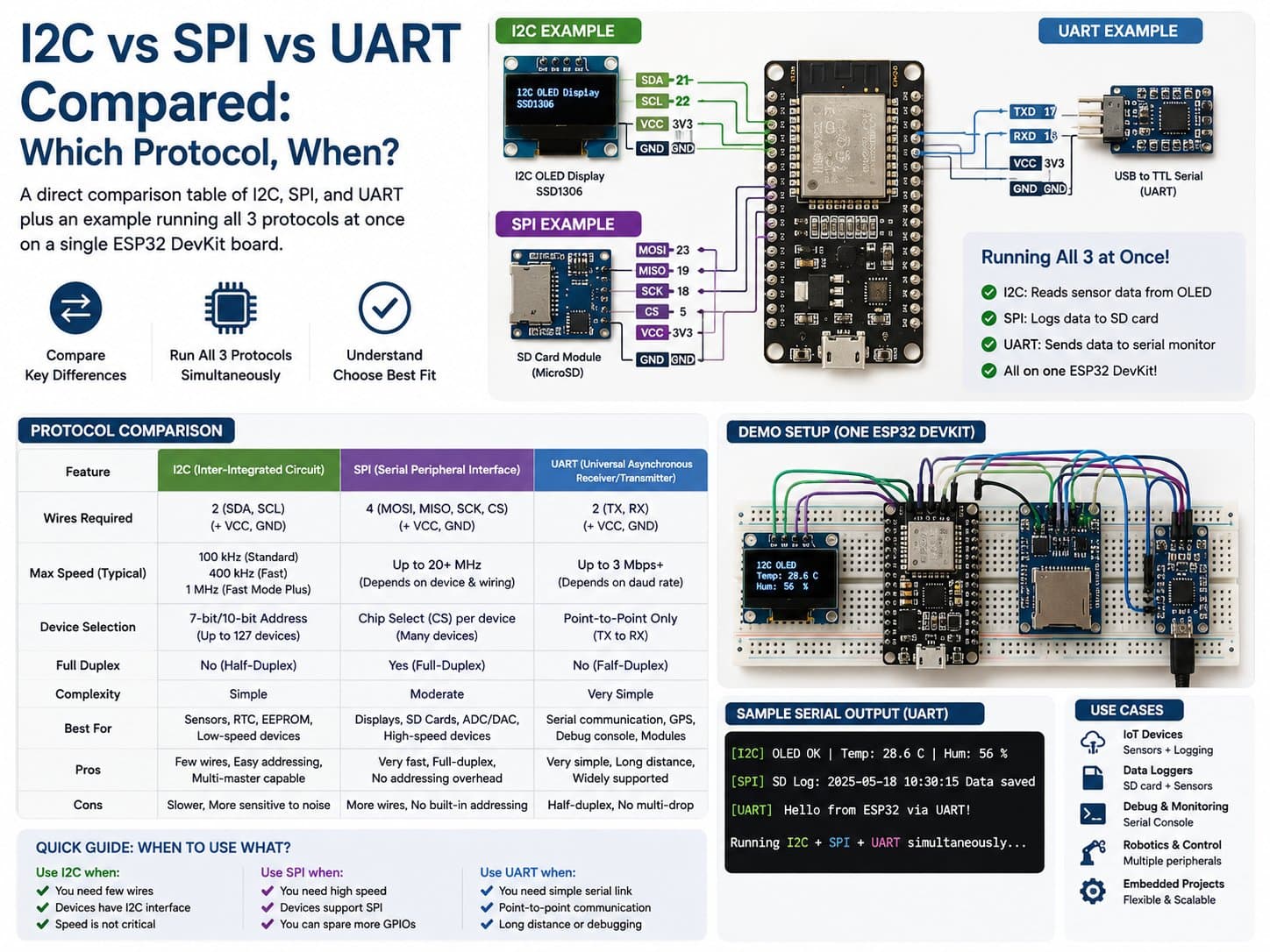
I2C vs SPI vs UART Compared: Which Protocol, When?
A direct comparison table of I2C, SPI, and UART (wire count, speed, device selection) plus an example running all 3 protocols at once on a single ESP32 DevKit board.
The ESP32 supports all 3 of the most common wired communication protocols at once: I2C (2 shared wires, 7-bit addressing), SPI (4+ wires, devices selected by a dedicated CS pin, high speed), and UART (2 wires TX/RX, point-to-point communication between exactly 2 devices, no addressing).
This lesson pulls together the 3 previous lessons (I2C, SPI, UART) into a direct comparison table, while actually running all 3 protocols at once on a single ESP32 DevKit board: I2C with a BMP280, SPI with an ST7735 TFT display, and UART over the very USB-Serial port used for debugging.
Detailed guide
A direct comparison of I2C, SPI, and UART with an example running all 3 protocols simultaneously on a single ESP32.
1. Introduction
The three previous lessons covered each protocol in depth: I2C (2 shared wires, 7-bit addressing), SPI (4+ wires, devices selected by a CS pin, high speed), and UART (2 wires TX/RX, no addressing, point-to-point only).
This lesson pulls them together into a direct comparison table for quickly picking the right protocol, and demonstrates it experimentally: the ESP32 can run all 3 protocols in parallel on the same board, each serving a different device.
2. Components Needed
| Component | Qty | Role |
|---|---|---|
| ESP32 DevKit V4 | 1 | Main board, runs all 3 protocols |
| BMP280 (I2C) | 1 | Represents I2C |
| TFT 1.44" 128x128 SPI (ST7735) | 1 | Represents SPI |
| (no extra hardware needed for UART) | — | Uses the board's built-in USB-Serial port directly |
3. Wiring Diagram
| BMP280 (I2C) | ESP32 |
|---|---|
| VCC / GND | 3V3 / GND |
| SDA | GPIO21 |
| SCL | GPIO22 |
| TFT ST7735 (SPI) | ESP32 |
|---|---|
| VCC / GND | 3V3 / GND |
| SCL/SCK | GPIO18 |
| SDA/MOSI | GPIO23 |
| CS | GPIO14 |
| DC | GPIO27 |
| RST | GPIO26 |
UART needs no extra wiring — the very USB cable connecting the ESP32 to your computer is already a UART channel (UART0), used directly to view logs via the Serial Monitor.
4. Example #1 — Running All 3 Protocols at Once
A sketch that initializes both the BMP280 (I2C) and the ST7735 TFT (SPI) in setup(), while printing a log over Serial (UART) every 2 seconds, reading temperature over I2C and updating the SPI display at the same time — demonstrating that all 3 protocols run independently without conflict, even sharing a single microcontroller.
/*
  I2C vs SPI vs UART Compared — Example #1: 3 protocols on one board
  Board: ESP32 DevKit V4
    - I2C : BMP280 at 0x76        SDA=GPIO21 SCL=GPIO22
    - SPI : TFT ST7735 128x128    SCK=GPIO18 MOSI=GPIO23 CS=GPIO14 DC=GPIO27 RST=GPIO26
    - UART: the ESP32 DevKit's built-in USB-Serial port (UART0, GPIO1/GPIO3) -
            no extra hardware needed, just use Serial.begin() below.

  Lesson goal: the same board can run all 3 bus types at once,
  illustrating the difference in wire count and how devices are addressed.
*/

#include <Wire.h>
#include <SPI.h>
#include <Adafruit_BMP280.h>
#include <Adafruit_GFX.h>
#include <Adafruit_ST7735.h>

#define I2C_SDA 21
#define I2C_SCL 22
#define BMP280_ADDR 0x76

#define TFT_CS 14
#define TFT_DC 27
#define TFT_RST 26

Adafruit_BMP280 bmp;
Adafruit_ST7735 tft = Adafruit_ST7735(TFT_CS, TFT_DC, TFT_RST);

void setup() {
  // UART: the built-in Serial USB, no dedicated wire needed - the simplest UART example
  Serial.begin(115200);
  delay(300);
  Serial.println(F("=== So sanh I2C / SPI / UART tren 1 board ==="));
  Serial.println(F("[UART] Serial USB dang chay 115200 baud (day nay chinh la UART0)"));

  // I2C: 2 day dung chung, dia chi hoa bang so 7-bit
  Wire.begin(I2C_SDA, I2C_SCL);
  bool bmpOk = bmp.begin(BMP280_ADDR);
  Serial.printf("[I2C] BMP280 tai 0x76: %s (SDA=%d SCL=%d)\n", bmpOk ? "OK" : "KHONG THAY", I2C_SDA, I2C_SCL);

  // SPI: nhieu day, moi thiet bi co CS rieng thay vi dia chi
  tft.initR(INITR_144GREENTAB);
  tft.fillScreen(ST77XX_BLACK);
  tft.setRotation(1);
  tft.setTextColor(ST77XX_WHITE);
  tft.setTextSize(1);
  tft.setCursor(4, 4);
  tft.println("I2C+SPI+UART");
  Serial.printf("[SPI] TFT ST7735: da khoi tao (SCK=18 MOSI=23 CS=%d DC=%d RST=%d)\n", TFT_CS, TFT_DC, TFT_RST);
}

void loop() {
  static unsigned long lastLoop = 0;
  if (millis() - lastLoop >= 2000) {
    lastLoop = millis();

    float tempC = bmp.readTemperature();
    Serial.printf("[UART->PC] Bao cao: [I2C] temp=%.1fC | [SPI] man hinh dang hien thi\n", tempC);

    tft.fillRect(4, 20, 110, 20, ST77XX_BLACK);
    tft.setCursor(4, 20);
    tft.printf("I2C T=%.1fC", tempC);
  }
}
5. Example #2 — Measuring Real I2C vs SPI Speed
A second variant that uses micros() to measure the actual duration of a single I2C read transaction (BMP280) versus a single SPI write command (drawing a colored square on the TFT), printing the results over UART so you can compare with real numbers instead of just reading datasheet figures.
/*
  I2C vs SPI vs UART Compared — Example #2: measuring real transfer speed of I2C and SPI
  Board: ESP32 DevKit V4 (same wiring as example #1)
  Prints over UART (Serial Monitor) the time (in microseconds) for each I2C read
  and SPI write, so you can compare with real numbers instead of just datasheet figures.
*/

#include <Wire.h>
#include <SPI.h>
#include <Adafruit_BMP280.h>
#include <Adafruit_GFX.h>
#include <Adafruit_ST7735.h>

#define I2C_SDA 21
#define I2C_SCL 22
#define BMP280_ADDR 0x76

#define TFT_CS 14
#define TFT_DC 27
#define TFT_RST 26

Adafruit_BMP280 bmp;
Adafruit_ST7735 tft = Adafruit_ST7735(TFT_CS, TFT_DC, TFT_RST);

void setup() {
  Serial.begin(115200);
  delay(300);
  Serial.println(F("=== Do toc do I2C (100kHz) vs SPI ==="));

  Wire.begin(I2C_SDA, I2C_SCL);
  Wire.setClock(100000); // I2C Standard-mode 100kHz
  bmp.begin(BMP280_ADDR);

  tft.initR(INITR_144GREENTAB);
  tft.setSPISpeed(4000000); // SPI 4MHz - much faster than I2C
  tft.fillScreen(ST77XX_BLACK);
}

void loop() {
  unsigned long t0 = micros();
  float tempC = bmp.readTemperature(); // 1 giao dich I2C hoan chinh
  unsigned long i2cDurationUs = micros() - t0;

  unsigned long t1 = micros();
  tft.fillRect(0, 0, 20, 20, ST77XX_RED); // 1 lenh ghi SPI len man hinh
  unsigned long spiDurationUs = micros() - t1;

  Serial.printf("[I2C] doc BMP280: %lu us | [SPI] ve o mau: %lu us | T=%.1fC\n",
                i2cDurationUs, spiDurationUs, tempC);

  delay(1500);
}
6. Summary Comparison Table — Which Protocol, When?
| Criterion | I2C | SPI | UART |
|---|---|---|---|
| Signal wire count | 2 (SDA, SCL) | 4+ (SCK, MOSI, MISO, CS per device) | 2 (TX, RX) |
| Devices per bus | Many (limited by 7-bit address, ~112 values) | Many (limited by available CS pins) | Exactly 2 (point-to-point) |
| How a device is selected | An address in the data frame | A physical CS pin | Not needed (only 1 connection) |
| Typical speed | 100k–400kHz | A few MHz – tens of MHz | 9600 – 921600 bps (baud) |
| Synchronous | Yes (SCL wire) | Yes (SCK wire) | No (baud rate must be agreed beforehand) |
| Best used for | Many small sensors, saving pins | Displays, memory cards, when high bandwidth is needed | Point-to-point links, GPS/SIM/RS232 modules |
7. Common Issues
| Issue | Cause | Fix |
|---|---|---|
| The board hangs when running all 3 protocols together | Overlapping GPIO pins between buses (e.g. accidentally reusing GPIO18 for something else) | Carefully check the pin-allocation table, avoiding overlap between I2C/SPI/UART/plain GPIO |
| Not sure which protocol to pick for a new design | Haven't clarified: many devices needed, or high speed, or just 2 devices | Use the table in section 6: many small devices → I2C; high bandwidth → SPI; 2 simple devices → UART |
| A device only supports one protocol, but the board is out of suitable pins | Pin allocation wasn't planned upfront for every protocol needed | Map out the full pin diagram before soldering/wiring for real |
8. Summary
No protocol is universally "best" — each is optimized for a different need: I2C saves pins with many small devices, SPI wins on speed when high bandwidth is needed, UART is simplest when connecting exactly 2 devices.
In practice, most IoT projects combine all three: I2C for sensors, SPI for displays/storage, UART for GPS/SIM modules or debugging — exactly as shown in this lesson's example.