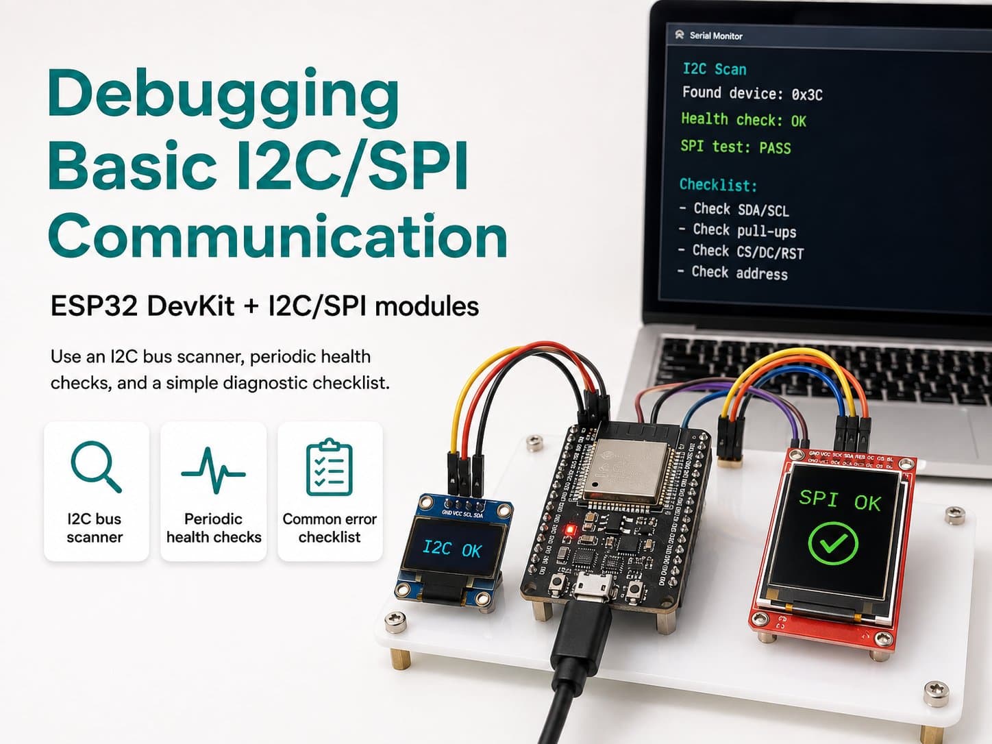
Debugging Basic I2C/SPI Communication
I2C/SPI debugging techniques without specialized test equipment: an I2C bus scanner, periodic health-checks, and a diagnostic checklist for common errors with the ESP32 DevKit.
I2C and SPI are both "silent on failure" protocols: when the wiring is wrong, pull-up resistors are missing, or the address is wrong, the device usually doesn't report a clear error — it simply doesn't respond, which makes it easy for beginners to confuse a hardware fault, a library bug, or a code mistake.
This lesson focuses on debugging techniques that are entirely software-based, requiring no logic analyzer or oscilloscope: using the ESP32 itself as the diagnostic tool via an I2C bus scanner (scanning the whole address range to see which devices are actually responding) and periodic health-checks (catching early when a device "drops off" the bus mid-session).
This is a foundational skill worth having before diving into debugging any I2C/SPI project.
Detailed guide
Software-only I2C/SPI debugging techniques with no test equipment needed: an I2C bus scanner, periodic health-checks, and a diagnostic checklist for common errors.
1. Introduction
Both I2C and SPI are "silent on failure" protocols: if the wiring is wrong, pull-ups are missing, or the address is wrong, the device doesn't report an error on its own — it simply doesn't respond, leading to vague messages like "sensor not found" that leave beginners unsure where to start looking. The debugging techniques in this lesson need no logic analyzer or oscilloscope, using only the ESP32 and code to diagnose: most important is the I2C bus scanner — the first tool to reach for whenever you suspect an I2C problem.
The bus scanner's principle is simple: I2C has an ACK/NACK mechanism at the hardware level — send any address, and if a device is listening at that address, it automatically pulls SDA low to ACK. The scanner just needs to try all 112 valid addresses (0x08-0x77) in turn and record which ones ACK — no need to know in advance what the device is or which library it uses.
2. Components Needed
| Component | Qty | Note |
|---|---|---|
| ESP32 DevKit V4 | 1 | Main board |
| BMP280 (I2C) | 1 | Sample device to scan, address 0x76 |
| 0.96" I2C OLED (SSD1306) | 1 | Second sample device, address 0x3C |
3. Wiring Diagram
| BMP280 & OLED | ESP32 |
|---|---|
| VCC | 3V3 |
| GND | GND |
| SDA | GPIO21 (shared wire) |
| SCL | GPIO22 (shared wire) |
This is the same diagram as the "What is I2C?" lesson — reused deliberately so the focus stays on debugging technique rather than new hardware. The bus scanner works with any I2C device, not just these two.
4. Example #1 — Full I2C Bus Scanner
A sketch that scans all 112 valid addresses every 5 seconds, printing which ones ACK (err == 0), flagging abnormal transmission errors (err == 4, usually noise/a loose wire), and skipping normal NACKs (err == 2, simply no device present) to keep the log clean. If no device is found, it also prints a 3-step checklist.
/*
  Debugging Basic I2C/SPI Communication — Example #1: Full I2C Bus Scanner
  Board: ESP32 DevKit V4 + BMP280 (0x76) + OLED SSD1306 (0x3C) on the same I2C bus
  SDA=GPIO21 SCL=GPIO22

  This is the first debugging tool to run when I2C "can't see any device":
  scan all 112 valid addresses (0x08-0x77) and report which ones ACK.
  No need to know the device type / library in advance - just correct wiring.
*/

#include <Wire.h>

#define SDA_PIN 21
#define SCL_PIN 22

void setup() {
  Serial.begin(115200);
  delay(300);
  Serial.println(F("=== I2C Bus Scanner (debug tool) boot ==="));
  Serial.printf("SDA=GPIO%d SCL=GPIO%d, 100kHz Standard-mode\n", SDA_PIN, SCL_PIN);

  Wire.begin(SDA_PIN, SCL_PIN);
  Wire.setClock(100000);
}

void scanOnce() {
  Serial.println(F("--- Bat dau quet ---"));
  uint8_t found = 0;

  for (uint8_t addr = 0x08; addr <= 0x77; addr++) {
    Wire.beginTransmission(addr);
    uint8_t err = Wire.endTransmission();

    if (err == 0) {
      Serial.printf("  [OK]  0x%02X - thiet bi phan hoi ACK\n", addr);
      found++;
    } else if (err == 4) {
      // err=4: loi khong xac dinh khi truyen - thuong la nhieu/day loi tai dia chi nay
      Serial.printf("  [ERR] 0x%02X - loi khong xac dinh (kiem tra day/nhieu)\n", addr);
    }
    // err == 2 (NACK dia chi) la binh thuong: khong co thiet bi tai dia chi do, khong in de do log
  }

  if (found == 0) {
    Serial.println(F("[WARN] Khong tim thay thiet bi nao. Kiem tra:"));
    Serial.println(F("  1) Da co dien tro pull-up SDA/SCL chua (thuong co san tren module)"));
    Serial.println(F("  2) SDA/SCL co bi noi nguoc nhau khong"));
    Serial.println(F("  3) VCC module co dung 3.3V khong (mot so module can 5V)"));
  } else {
    Serial.printf("--- Ket thuc: tim thay %u thiet bi ---\n", found);
  }
}

void loop() {
  scanOnce();
  delay(5000); // quet lai moi 5s, huu ich khi dang ro day/hot-plug de debug
}
5. Example #2 — Periodic Health-Check for 2 Known Devices
Once you're certain of a device's address (unlike example #1, where nothing is known yet), use a periodic "ping" every 3 seconds to catch early if a device drops off the bus mid-session — a classic sign of a loose wire or noise, quite different from a wrong-address error (which fails from the very start rather than "working, then dropping out").
/*
  Debugging Basic I2C/SPI Communication — Example #2: Periodic Health-Check for 2 Known Devices
  Board: ESP32 DevKit V4 + BMP280 (0x76) + OLED SSD1306 (0x3C)
  Once you already know a device's address, use a periodic "ping" test to catch
  early when a device drops off the bus (loose wire, noise) instead of waiting
  for the main code to throw a confusing error.
*/

#include <Wire.h>

#define SDA_PIN 21
#define SCL_PIN 22
#define BMP280_ADDR 0x76
#define OLED_ADDR 0x3C

bool pingAddr(uint8_t addr) {
  Wire.beginTransmission(addr);
  return Wire.endTransmission() == 0;
}

void setup() {
  Serial.begin(115200);
  delay(300);
  Serial.println(F("=== I2C Health-check (debug dinh ky) boot ==="));
  Wire.begin(SDA_PIN, SCL_PIN);
  Wire.setClock(100000);
}

void loop() {
  bool bmpOk = pingAddr(BMP280_ADDR);
  bool oledOk = pingAddr(OLED_ADDR);

  Serial.printf("[HEALTH] BMP280(0x76)=%s  OLED(0x3C)=%s\n",
                bmpOk ? "OK" : "MAT KET NOI",
                oledOk ? "OK" : "MAT KET NOI");

  if (!bmpOk || !oledOk) {
    Serial.println(F("[HINT] Neu vua OK roi mat dot ngot -> nghi ngo day long/nhieu,"));
    Serial.println(F("       khong phai loi dia chi (dia chi sai se mat ngay tu dau)."));
  }

  delay(3000);
}
6. Debugging SPI — How It Differs from I2C
SPI has no hardware-level ACK/NACK mechanism like I2C, so you can't write a similar "SPI scanner". Common software SPI debugging techniques: (1) read an ID register if the chip supports it (many ICs, like displays, offer a "device ID" read command over MISO to confirm you're talking to the right chip); (2) test each CS/DC/RST pin individually with digitalWrite + a temporary LED if you suspect a wrong pin; (3) try lowering the SPI speed (setSPISpeed) — if the error goes away at a lower speed, the cause is usually wire length or noise at high speed, not a wrong pin.
7. Common Issues
| Issue | Cause | Fix |
|---|---|---|
| The scanner finds no devices at all | Missing pull-ups, SDA/SCL swapped, or wrong VCC voltage | Work through the 3-step checklist the scanner prints when found == 0 |
The scanner reports [ERR] at some addresses | Electrical noise or poor wire contact (error code 4) | Recheck the connectors, shorten the wires, keep them away from noise sources (motors, relays) |
| A device shows up intermittently in the health-check | A loose wire or poor breadboard contact, not an address error | Check the mechanical connections: press the wires/module in firmly, try a different breadboard/wire |
| The scanned address differs from the datasheet | The module's address-configuration pin (e.g. the BMP280's SDO) is in a non-default state | Check the actual address-configuration pin on the physical module, don't rely on the datasheet alone |
8. Summary
Effective I2C/SPI debugging starts by confirming the lowest layer before suspecting the code or the library: for I2C, running the bus scanner first is always the right move — it clearly separates a "hardware/wiring problem" from a "code logic problem".
For SPI, since there's no ACK mechanism, you have to rely on reading a chip ID (if available) or observing behavior as you change speed/pins. This skill applies to any I2C/SPI project, not just the BMP280/OLED used in this lesson.