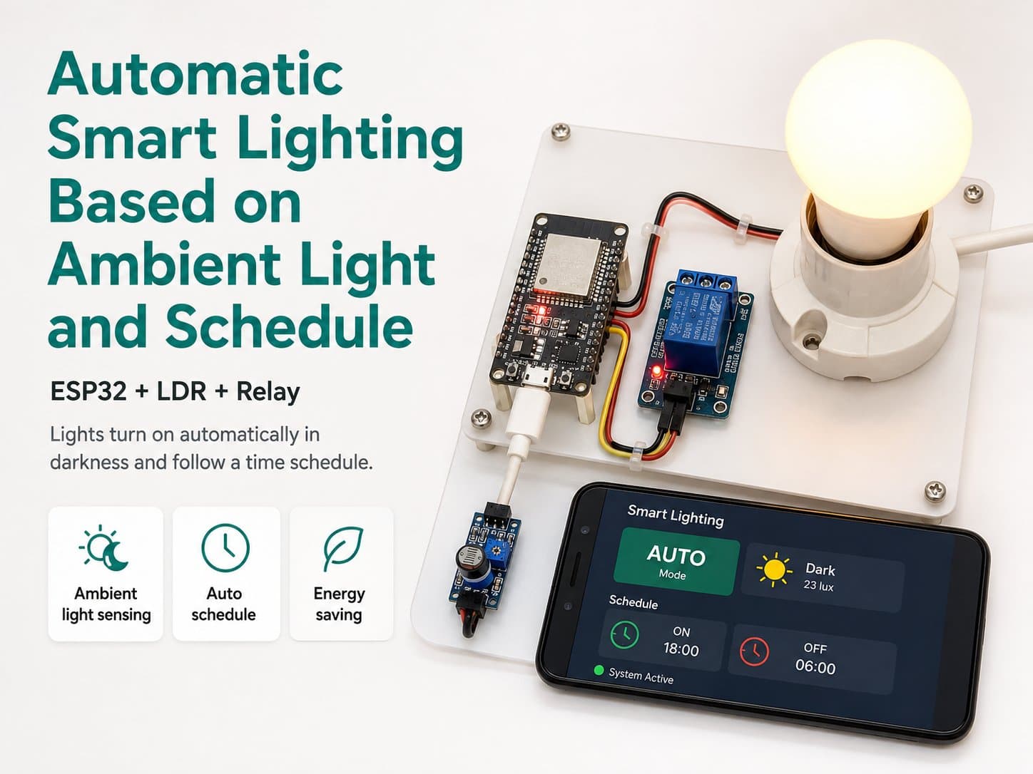
Automatic Smart Lighting Based on Ambient Light and Schedule
ESP32 automatically turns an LED/relay light on or off based on an LDR light sensor and an NTP-synced schedule — it only turns on when it's dark out and within the configured time window.
This project turns an ordinary bulb or LED strip into a "smart" light: the ESP32 reads ambient light through an LDR photoresistor, and syncs real time via NTP to know the current time of day.
The light only turns ON automatically when it's dark enough outside and within the configured schedule window (e.g. 6:00 PM–11:00 PM).
Detailed guide
ESP32 automatically turns an LED strip on or off based on an LDR light sensor and an NTP-synced schedule.
1. Introduction
This project turns a 12V/5V LED strip into a "smart" light: the ESP32 reads ambient light through an LDR photoresistor, while syncing real time via NTP to know the current time of day. Using a 12V/5V LED strip as the standard load keeps this build completely safe, with no risk of electric shock.
The light only turns ON automatically when it's dark out and within the configured schedule window (e.g. 6:00 PM–11:00 PM), avoiding a false trigger on an overcast day and preventing the light from staying on all night outside the intended hours.
2. Components Needed
| Component | Qty | Notes |
|---|---|---|
| ESP32 DevKit V4 | 1 | The main board, handling logic + WiFi |
| LDR — Photoresistor Sensor (mod_ldr_analog) | 1 | Reads the light level via its Analog output (AO) |
| Relay Module 1 kênh 5V (mod_relay_1ch) | 1 | Switches power to the LED strip, active-low |
| 12V LED strip (or a 5V LED light) + its own power adapter | 1 | The project's standard load — safe, with no shock risk |
3. Wiring Diagram
| Module pin | ESP32 |
|---|---|
| LDR VCC | 3V3 |
| LDR GND | GND |
| LDR AO | GPIO34 (ADC input-only) |
| Relay VCC | 5V |
| Relay GND | GND |
| Relay IN | GPIO26 |
| Relay NO/COM | The 12V/5V LED strip's positive (+) wire, powered from its own adapter — not from the ESP32 |
Note: the relay module only needs 5V/GND/IN connected to the ESP32 — its NO/COM terminals wire directly into the LED strip's power line (an external supply); never connect AC mains to an ESP32 GPIO pin. The DARK_THRESHOLD value should be calibrated in the real environment for your specific LDR voltage-divider circuit.
4. Example #1 — Reading the LDR Light Sensor (ADC)
void setup() {
  Serial.begin(115200);
  pinMode(PIN_LDR_AO, INPUT);
}

void loop() {
  int ldrValue = analogRead(PIN_LDR_AO); // 0-4095, lower = darker
  bool isDark = ldrValue < DARK_THRESHOLD;
  Serial.printf("ldr=%d dark=%s\n", ldrValue, isDark ? "true" : "false");
  delay(500);
}
5. Example #2 — Controlling the Relay Based on Light + NTP Schedule
void setRelay(bool on) {
  // Relay active-low: IN=LOW => kích hoạt (đóng NO, bật đèn)
  digitalWrite(PIN_RELAY_IN, on ? LOW : HIGH);
  relayState = on;
}

bool inSchedule(struct tm &timeinfo) {
  int hour = timeinfo.tm_hour;
  return (hour >= SCHEDULE_START_HOUR && hour < SCHEDULE_END_HOUR);
}

// Trong loop(): bật đèn khi VỪA tối VỪA trong khung giờ lịch
bool shouldTurnOn = isDark && inSchedule(timeinfo);
if (shouldTurnOn != relayState) setRelay(shouldTurnOn);
6. Example #3 — The Complete Application: WiFi + NTP + LDR + Relay
/*
  Đèn chiếu sáng thông minh tự động theo ánh sáng và lịch giờ
  Board: ESP32 DevKit V4 (board_esp32_devkitc)
  - LDR (mod_ldr_analog)  AO -> GPIO34
  - Relay 1 kênh (mod_relay_1ch) IN -> GPIO26 (điều khiển dải LED 12V/5V qua tải DC)

  Đèn sẽ bật khi: trời tối (LDR đọc dưới ngưỡng) VÀ đang trong khung giờ lịch (vd 18:00-23:00).
  Ngoài khung giờ hoặc trời đủ sáng -> tắt.
*/

#include <WiFi.h>
#include <time.h>

const char *WIFI_SSID = "YOUR_WIFI_SSID";
const char *WIFI_PASSWORD = "YOUR_WIFI_PASSWORD";

const int PIN_LDR_AO = 34;
const int PIN_RELAY_IN = 26;

const int DARK_THRESHOLD = 1800;
const int SCHEDULE_START_HOUR = 18;
const int SCHEDULE_END_HOUR = 23;

const char *NTP_SERVER = "pool.ntp.org";
const long GMT_OFFSET_SEC = 7 * 3600;
const int DAYLIGHT_OFFSET_SEC = 0;

const unsigned long WIFI_RETRY_INTERVAL_MS = 5000;
const unsigned long WIFI_CONNECT_TIMEOUT_MS = 10000;
const unsigned long TELEMETRY_INTERVAL_MS = 5000;

unsigned long lastWifiAttemptMs = 0;
unsigned long lastTelemetryMs = 0;
bool relayState = false;
bool ntpSynced = false;

void connectWiFiNonBlocking() {
  if (WiFi.status() == WL_CONNECTED) return;
  unsigned long now = millis();
  if (now - lastWifiAttemptMs < WIFI_RETRY_INTERVAL_MS) return;
  lastWifiAttemptMs = now;

  WiFi.mode(WIFI_STA);
  WiFi.begin(WIFI_SSID, WIFI_PASSWORD);

  unsigned long start = millis();
  while (WiFi.status() != WL_CONNECTED && millis() - start < WIFI_CONNECT_TIMEOUT_MS) {
    delay(200);
  }

  if (WiFi.status() == WL_CONNECTED) {
    if (!ntpSynced) {
      configTime(GMT_OFFSET_SEC, DAYLIGHT_OFFSET_SEC, NTP_SERVER);
      struct tm timeinfo;
      if (getLocalTime(&timeinfo, 5000)) {
        ntpSynced = true;
      }
    }
  }
}

void setRelay(bool on) {
  digitalWrite(PIN_RELAY_IN, on ? LOW : HIGH);
  relayState = on;
}

void setup() {
  Serial.begin(115200);
  delay(300);
  pinMode(PIN_LDR_AO, INPUT);
  pinMode(PIN_RELAY_IN, OUTPUT);
  setRelay(false);
  connectWiFiNonBlocking();
}

void loop() {
  connectWiFiNonBlocking();

  int ldrValue = analogRead(PIN_LDR_AO);
  bool isDark = ldrValue < DARK_THRESHOLD;

  bool inSchedule = false;
  struct tm timeinfo;
  bool haveTime = ntpSynced && getLocalTime(&timeinfo, 10);
  if (haveTime) {
    int hour = timeinfo.tm_hour;
    inSchedule = (hour >= SCHEDULE_START_HOUR && hour < SCHEDULE_END_HOUR);
  }

  bool shouldTurnOn = isDark && inSchedule;
  if (shouldTurnOn != relayState) {
    setRelay(shouldTurnOn);
  }

  delay(200);
}
7. Common Issues
| Issue | Cause | Fix |
|---|---|---|
| The LDR always reads a fixed value (0 or 4095) | Wrong AO pin, or the input-only pin is being used for something else by mistake | Check that GPIO34 isn't already in use, and probe the AO pin with a multimeter while covering/exposing it to light |
| The relay clicks but the light doesn't turn on | NO/NC wired backwards, or the load exceeds the relay's rated current | Use the NO terminal for a circuit that should turn on when activated; check that the load current suits the LED strip |
| NTP never syncs (time is always stuck at 1970) | WiFi times out before configTime() has a chance to run | Try a different NTP server (e.g. time.google.com), and make sure the network doesn't block UDP port 123 |
| The light flickers on/off repeatedly around the dark threshold | The LDR reading oscillates around DARK_THRESHOLD with no hysteresis | Add a hysteresis band — e.g. use a different on-threshold and off-threshold, ±100 apart |
8. Summary
You now have a light that turns on automatically based on both real light conditions and a desired schedule, using two common modules (LDR + Relay) with a safe 12V/5V LED strip as the standard load, and the ESP32's built-in NTP support.
Possible extensions: multiple schedule windows, app/MQTT control, or PWM+MOSFET dimming instead of a hard on/off switch.